
Installation Instructions Owner's manual

Publication 1771-IN072B-EN-P - December 2004 4 PN 957944-28
Supersedes Publication 1771-2.116 - April 1992 and 1771-IN072A - January 2001 © 2004 Rockwell International Corporation. Printed in the U.S.A.
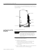
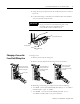
4. Replace the fuse holder in the field wiring arm as shown above.
5. Reapply power to the wiring arm.
Specifications
WARNING
The 1771-WHF and 1771-WHFB are not suitable for use
in Class I Division 2 Groups A, B, C, D Environments.
Catalog Number 1771-WHF (3 A) and 1771-WHFB (1.5 A)
Dimensions 8.265H x 1.224W x 2.0D (inches)
209H x 31W x 51D (millimeters)
Conductors
Wire Size - 14…20 AWG (2.5mm
2
…0.5mm
2
), copper only
stranded or solid, rated at 75
o
C or higher,
3/64 inch (1.22mm) insulation
Category - Refer to specific module installation instructions
Fuses 1771-WHF - Littelfuse 2AG 3 A Part No. 225003
1771-WHFB - Littelfuse 2AG 1.5 A Part No. 22501.5
Optional Fuse Pak 1771-WHF - Cat. No. 1771-FD: contains 2 fuse holders and 8 2AG 3 A
fuse
s
1771-WHFB - Cat. No. 1771-FD2: contains 2 fuse holders and 8 2AG
1.5 A fuses
Wiring Arm Screw Torque 9 pound-inches
Terminal Rating Terminals A-D rated for 8 A @ 250V
1771-WHF - Terminal 00…17 - 3.0 A, 250V per terminal with a
maximum of 12 A combined for terminals 00…17 derated linearly
from 10 °C to 2 A per terminal at 60 °C.
1771-WHFB - Terminal 00…17 - 1.5 A, 250V per terminal with a
maximum of 12 A combined for terminals 00…17.