
User Manual

Symbols
**Empty**, P-1, P-2, C-1, C-7, C-8
A
application considerations, C-8
B
bit/Word descriptions, 4-3
block transfer read
bit/word descriptions, 5-3
programming, 5-1
BTR, 3-1
bit/word description, 5-3
word assignments, 5-1
BTR length, E-1
BTW, 3-1
bit/word descriptions, 4-3
configuration block, 4-2
C
CE96 directives, 2-1
communication
between module and controller, 1-17
block transfers, 3-1
Compatibility, use of data table, P-2
configuration
block transfer write (BTW), 4-2
features, 4-1
configuration jumpers, setting the, 2-4
connecting wiring, field wiring arm, 2-5
continuous/rate mode, 1-12
counter mode
block diagram, 1-3
operation, 1-3
D
default configuration, 1-16
diagnostic indicators, 2-8
diagnostics, codes returned by module,
6-2
E
electrostatic discharge, 2-2
EMC directive, 2-1
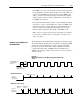
encoder, phase relationship, 1-6
encoder mode
block diagram, 1-4
direction of count, 1-5
operation, 1-2
encoder X4, 1-3
G
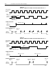
gate reset input, 1-7
grounding, 2-6
H
handshaking bits, 1-16
I
indicator lights, interpreting, 2-8
indicators, using for troubleshooting, 6-1
input cabling
capacitance, C-9
impedance, C-9
length and frequency, C-9
input devices
+12 to +24V single-ended driver, C-5
5V line driver, C-4
electromechanical limit switch, C-7
open collector, C-6
selecting, C-1
types of, C-1
installing the module, 2-7
K
keying bands, location, 2-3
keying your module, 2-3
L
low voltage directive, 2-1
Index