
User Manual

Application ConsiderationsC–6
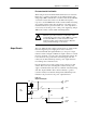
Open Collector
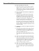
Open collector circuits (the upper circuit in Figure C.3) require close
attention so that the input voltage is sufficient to produce the
necessary source current, since it is limited not only by the
1771-VHSC input resistors but also the open collector pull-up.
Jumper position provides some options as shown in the table below.
Supply Voltage verses Jumper Settings
Supply Voltage Jumper Setting Total Impedance Available Current
+12 JPR4 3.15K 3.2mA (insufficient)
+12 JPR5 2.15K 4.65mA (insufficient)
+24 JPR4 3.15K 7mA (optimal)
+24 JPR5 2.15K 10.2mA (okay)
In this example, you must increase the supply voltage above +12V to
make sure there is sufficient input current to overcome the additional
2K source impedance. Note that there is insufficient current with the
jumper in the 12-24V position and a +12V supply.
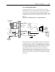
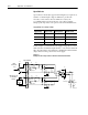
Figure C.3
Example Circuits for Open Collector and Electromechanical Limit Switch
R1 R2
C41
JPR4 JPR5
JPR6
JPR7
JPR8 JPR9
JPR10
JPR11
R3 R4
R97 R98
C43
Q2
Q3
D2
D1
D4
D3
R100
R101
R31
R36
C38
C42
+5V
C3 C4
1
2
3
4
1501K
+12V
INPUT
OUTPUT
GROUND
OPEN
COLLECTOR
LIMIT
SWITCH OR
DC PROXIMITY
SWITCH
+12 T
O +24V
POWER
SUPPLY
SWITCH
GROUND
1501K
40.2 40.2
40.2 40.2
Input Terminals
Voltage
Jumpers
Filter Jumpers
V
oltage Jumpers
2K
10692I