
User Manual

Chapter 6
Troubleshooting
In this chapter you will learn how to troubleshoot your VHSC
module using the indicators on the front of the module, and the
troubleshooting flowchart.
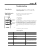
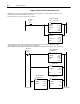
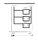
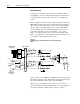
The indicators on the front of the module are an aid in
troubleshooting. These indicators consist of:
• active indicator
• input indicators
• output indicators
• fault indicator
The active indicator is on when the module has successfully powered
up. When an input indicator (A, B) is on, it indicates that the input is
high. When the output indicator is on, it indicates that the module
has commanded the output to be on. When a gate/reset indicator (G)
is on, its input is high. Since that signal can be inverted, it does not
indicate whether the signal on that terminal is necessarily logically
true.
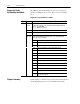
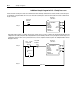
A troubleshooting chart is shown below.
Troubleshooting Chart
Indication Probable Cause Corrective Action
Active LED ON The module has successfully powered up. Normal. No action required.
Active OFF The module has not powered up successfully. Check fault light, and rack power supply.
Input LED ON A signal is available at the designated input
terminal (high).
Normal. No action required.
Input LED OFF A signal is not available at the designated input
terminal (low).
Normal. No action required.
Fault LED ON Internal problem. Power down the module, reseat in I/O chassis, and
restore power. If the fault LED remains on, replace
module.
Output LED ON The module has commanded an output on. Normal. No action required.
Output LED OFF The output is off. Normal. No action required.
Chapter Objectives
Using the Indicators for
Troubleshooting
A0 A1 A2 A3
B0 B1 B2 B3
00 02 04 06
01 03 05 07
ACTIVE
INPUTS
FAULT
OUTPUTS
Input Indicators
Output Indicators
Fault Indicator
Active Indicator
G0 G1 G2 G3
10716I