
User Manual

5–3
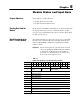
Module Status and Input Data
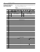
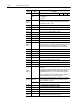
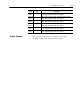
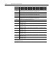
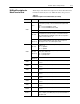
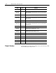
Table 5.B provides bit/word descriptions for the block transfer read
instruction returned by the 1771-VHSC module to the processor.
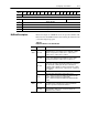
Table 5.B
Bit/W
ord Description for the VHSC Module (1771VHSC)
Word Bit Definition
Bit 00
Powerup bit indicates whether a successful BTW with valid data has
occurred since powerup, or since last switched from Program to Run
mode.
Bit = 0 A successful BTW has occurred
Bit = 1 A successful BTW has not occurred
Word 1
Bits 0103
Not used
Bits 0407
New data bits. Indicates that a store register (BTR words 1118) has
been updated. These bits are reset by a 0 to 1 transition of the new
data acknowledge bits in BTW word 1, bits 47. Bit 04 corresponds to
counter 0, bit 05 to counter 1, etc.
Bits 0815
(Bits 1017)
Diagnostic byte. Always in BCD. This byte indicates the number of the
first word in the BTW file that was incorrect. Refer to chapter 7 for
other diagnostic error codes returned by the module.
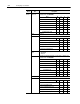
Bits 0007
Status bits for outputs. Bit 00 corresponds to output 0, bit 01 to
counter 2, etc.
Bit = 0 output OFF
Bit = 1 output ON
Word 2
Bits 0811
(Bits 1012)
State of gate/reset input. Bit 08 (10) corresponds to counter 0,
bit 09 (11) to counter 1, etc.
Bit = 0 gate input inactive
Bit = 1 gate input active
Bits 1215
(Bits 1317)
Not used
Word 3
Contains the most significant digit for counter 0. The allowable range
is 0999.
Word 4
Contains the least significant digit for counter 0. The allowable range
is 0999.
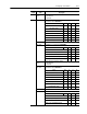
Word 5
Contains the most significant digit for counter 1. The allowable range
is 0999.
Word 6
Contains the least significant digit for counter 1. The allowable range
is 0999.
Word 7
Contains the most significant digit for counter 2. The allowable range
is 0999.
Word 8
Contains the least significant digit for counter 2. The allowable range
is 0999.
Word 9
Contains the most significant digit for counter 3. The allowable range
is 0999.
Word 10
Contains the least significant digit for counter 3. The allowable range
is 0999.
Words 11
Counter 0 Store count values MSD (range 0999) in encoder/counter
mode; or frequency value MSD (range 0500) in rate measurement or
period/rate mode
Bit/Word Description for
Block Transfer Read