
User Manual

5–2
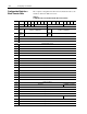
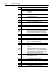
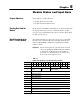
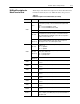
Module Status and Input Data
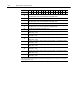
00010203040506071011121314151617(Octal Bit)
00010203040506070809101112131415Decimal Bit
13
Counter 1 Store count values MSD (range 0999) in encoder/counter mode; or frequency
value MSD (range 0500) in rate measurement or period/rate mode
14 Counter 1 Store count values LSD (range 0999)
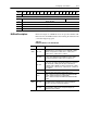
15
Counter 2 Store count values MSD (range 0999) in encoder/counter mode; or frequency
value MSD (range 0500) in rate measurement or period/rate mode
16 Counter 2 Store count values LSD (range 0999)
17
Counter 3 Store count values MSD (range 0999) in encoder/counter mode; or frequency
value MSD (range 0500) in rate measurement or period/rate mode
18 Counter 3 Store count values LSD (range 0999)
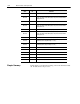
19
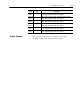
Counter 0 Total counts occurring at gate/reset pin in period/rate or continuous/rate modes
(MSD range = 0999)
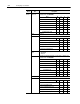
20
Counter 0 Total counts occurring at gate/reset pin in period/rate or continuous/rate modes
(LSD range = 0999)
21
Counter 1 Total counts occurring at gate/reset pin in period/rate or continuous/rate modes
(MSD range = 0999)
22
Counter 1 Total counts occurring at gate/reset pin in period/rate or continuous/rate modes
(LSD range = 0999)
23
Counter 2 Total counts occurring at gate/reset pin in period/rate or continuous/rate modes
(MSD range = 0999)
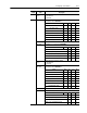
24
Counter 2 Total counts occurring at gate/reset pin in period/rate or continuous/rate modes
(LSD range = 0999)
25
Counter 3 Total counts occurring at gate/reset pin in period/rate or continuous/rate modes
(MSD range = 0999)
26
Counter 3 Total counts occurring at gate/reset pin in period/rate or continuous/rate modes
(LSD range = 0999)
*
PU
= Power up bit (refer to word/bit description)
Note:
Words 19 through 26 are optional and used only in period/rate and continuous/rate modes. They can only be accessed by making
the BTR length between 19 and 26.