
User Manual

4–6
Configuring Your Module
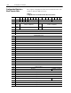
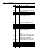
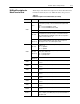
DescriptionBitsWord
Mode 4 (storereset/start) used 1 0 0
bit 15
Invert signal bit for gate/reset terminal.
0 = Not inverted
1 = Inverted
Words 5
thru 12
Rollover value. When rollover value is reached, the counter value
becomes 000,000 and counting continues from that point. The range
for both MSD and LSD is 0 to 999.
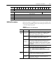
Word 5 Rollover value. Most significant digit for counter 0.
Word 6 Rollover value. Least significant digit for counter 0.
Word 7 Rollover value. Most significant digit for counter 1.
Word 8 Rollover value. Least significant digit for counter 1.
Word 9 Rollover value. Most significant digit for counter 2.
Word 10 Rollover value. Least significant digit for counter 2.
Word 11 Rollover value. Most significant digit for counter 3.
Word 12 Rollover value. Least significant digit for counter 3.
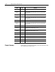
Words 13
thru 20
Preset values. The preset value is loaded into the respective counter
when its preset bit is set. The preset count value overrides the current
count, and becomes the new count value in the counter. When a
preset value is loaded, the counter begins to count from that value.
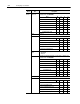
Word 13 Preset value. Most significant digit for counter 0.
Word 14 Preset value. Least significant digit for counter 0.
Word 15 Preset value. Most significant digit for counter 1.
Word 16 Preset value. Least significant digit for counter 1.
Word 17 Preset value. Most significant digit for counter 2.
Word 18 Preset value. Least significant digit for counter 2.
Word 19 Preset value. Most significant digit for counter 3.
Word 20 Preset value. Least significant digit for counter 3.
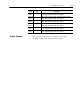
Words 21
thru 24
The ranges of words 21 thru 24 depend on the mode selected in word
3, bits 0002.
In encoder/counter mode or period/rate mode, these are scalar words,
and divide the incoming pulse train at the gate/reset terminal by a
predetermined integer (1, 2, 4, 8, 16, 32, 64 and 128). Default value
is 1.
In rate measurement mode, these are time base values. Range is in
milliseconds from 10ms to 2 seconds in 10ms intervals.
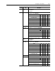
Word 25 bits 0003
Allows you to tie the output to any of the 4 counters. Bits correspond
to the counters: bit 00 for counter 0, bit 01 for counter 1, bit 02 for
counter 2, and bit 03 for counter 3.
bits 0415 Not used.
Word 26 Most significant digit of the ON value of output 0.
Word 27 Least significant digit of the ON value of output 0.
Word 28 Most significant digit of the OFF value of output 0.
Word 29 Least significant digit of the OFF value of output 0.
Words 30
thru 34
These words are a repeat of words 25 through 29 with the exception
of the output number. These words are for output 1.