
User Manual

2–6
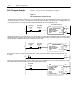
Installing the Very High-Speed Counter Module
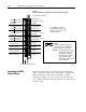
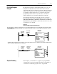
Figure 2.3
Connection Diagram for Very High Speed Counter Module (1771VHSC)
(See
applicable codes and laws.)
Note: Terminals on the left are
even numbered (2 thru 40), and
terminals on the right are odd
numbered (1 thru 39).
Channel A
/Channel A Return
Channel B
/Channel B Return
Gate Not input
Gate Not input
Channel A
/Channel A Return
Channel A
/Channel A Return
Channel B
/Channel B Return
Gate Not Input
Channel B Input
Channel A Input
Customer V
CC
01
Output
1
Output 3
Customer V
CC
45
Output
5
Customer V
CC
67
Output
0
Customer Common 01
Customer Common 23
Output 4
Customer Common 45
Output 6
Channel B Input
Gate Input
Gate Input
Channel A Input
Channel A Input
Channel B Input
Gate Input
2
4
6
8
10
12
14
16
18
20
22
24
26
28
30
32
34
36
38
40
Channel A Input
Channel B Input
Gate Input
Customer V
CC
23
Output
7
Channel B
/Channel B Return
Gate Not Input
Output 2
Customer Common 67
(Actual wiring runs in this direction.)
Counter 0
Counter 1
Counter 2
Counter 3
Channel A
/Channel A Return
Channel B
/Channel B Return
10689I
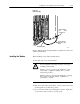
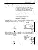
The sensor cable must be shielded. The
shield must:
•extend the length of the cable, but be
connected only at the 1771 I/O chassis
•extend up to the point of termination
Important:The shield should extend to the
termination point, exposing just
enough cable to adequately
terminate the inner conductors.
Use heat shrink or another
suitable insulation where the wire
exits the cable jacket.
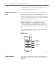
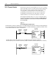
When using shielded cable, ground the foil shield and drain wire
only at one end of the cable. We recommend that you wrap the foil
shield and drain wire together and connect them to a chassis
mounting bolt (Figure 2.4). At the opposite end of the cable, tape
exposed shield and drain wire with electrical tape to insulate it from
electrical contact.
Grounding the VHSC
Module Wiring