
User Manual

2–5
Installing the Very High-Speed Counter Module
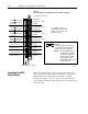
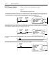
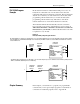
Figure 2.2
Setting the Configuration Jumpers
Filter Jumper
Position
Voltage Jumper
Position
Description of Operation
Down Down 1224V High Speed (factory default setting)
Down Up 5V High Speed
Up Down 1224V with low speed filter
Up Up 5V with low speed filter
FILTER
HI
SPEED
5V
1224V
A0
B0
G0
10688I
*
*
In the filter position, the module will not see frequencies above 100Hz.
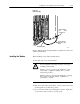
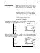
3.Reposition the cover and secure with the 4 screws removed in
step 1.
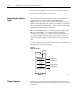
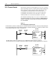
Connect your I/O devices to the 40-terminal field wiring arm (cat.
no. 1771-WN) shipped with the module (Figure 2.3). Attach the
field wiring arm to the pivot bar at the bottom of the I/O chassis.
The field wiring arm pivots upward and connects with the module so
you can install or remove the module without disconnecting the
wires.
Connecting Wiring