
User Manual

1–1
1Overview of the Very High Speed Counter Module
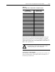
Table 1.A
Relationship
Between Sampled Pulses and Input Frequency
Input Frequency at Gate/Reset
Terminal in Hz
(words 1118 in BTR)
Sampled Pulses for 1/2 Cycle
of Gate/Reset Pulse
(words 310 in BTR)
2 1 meg
5 400K
10 200K
20 100K
50 40K
100 20K
200 10K
500 4K
1KHz 2K
2KHz 1K
5KHz 400
10KHz 200
20KHz 100
50KHz 40
100KHz 20
200KHz 10
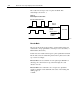
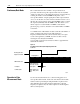
Operation of scaler
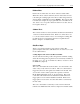
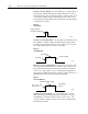
In period/rate mode, the scaler lets the incoming pulse train at the
gate/reset pin be divided by a user defined number. Acceptable
values for the scaler are 1, 2, 4, 8, 16, 32, 64 and 128. There is one
scaler value for each counter. The default value for each scaler is 1.
Note: A 0 is equivalent to 1.
!
ATTENTION: Sample period times scaler must be
less than 0.25 seconds or the counter will overflow
without providing an overflow indication.
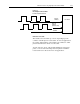
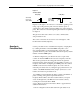
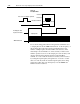
Connection to Counter Inputs
The only input to the module in the period/rate mode is made to the
gate/reset terminal. The counter inputs (channel A and B) are not
used in the period/rate mode.