
User Manual

1–9
Overview of the Very High Speed Counter Module
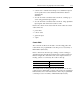
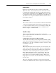
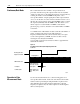
Figure 1.7
StoreReset/Start
Store Count,
reset to zero,
start counting.
Store Count,
reset to zero,
start counting.
Rising Edge
Falling Edge
10683I
Figures 1.4 through 1.7 show the store count feature operating on the
rising edge of the gate/reset pulse. The user has the option of
selecting these same features using the falling edge of the gate/reset
pulse. This selection is made through the gate invert bit as explained
in chapter 4.
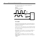
The gate invert bit is active in the store count, continuous/rate
and period/rate modes.
The stored count values are saved in words 11 through 18 of the
block transfer read file (chapter 4).
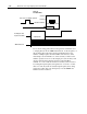
Use the period/rate mode to determine the frequency of input pulses
by counting the number of internal 4MHz clock pulses over a
user-specified number of input signal pulses. At the end of the
specified number of pulses, the module returns the frequency and the
number of internal 4MHz pulses.
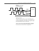
A channel configured for period/rate mode acts as a period rate
counter. An internal 4 MHz clock is used as a frequency reference.
This clock is gated by the incoming pulse train at the gate/reset
input. The results of this gating action are the number of pulses or a
frequency. The number of sampled gated 4MHz pulses are returned
in BTR words 3 thru 10, and the frequency in words 11 thru 18.
Select the period/rate mode by setting the appropriate bits in words
3 and 4 of the BTW initialization file (chapter 4). The store count
features are inactive in period/rate mode.
1771-VHSC revision B and later modules count the total number of
pulses occurring at the gate/reset pin. This function is
frequency-limited. This total count is returned when you request
words 19 through 26 in your BTR. You can reset this count by
resetting the reset bit (bits 0-4 in BTW
word 1). Rollover and preset are inactive. Refer to appendix E for
additional information.
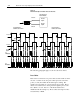
1.8 shows a diagram of the module used in the period/rate mode.
Operation in
Period/Rate Mode