
User Manual

1–6
Overview of the Very High Speed Counter Module
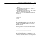
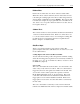
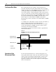
Figure 1.3
Phase Relationship for Forward or Reverse Directions
1 2 34 56789101112
Phase A
Phase B
X1
Multiplying
X4
Multiplying
123456789101112
0
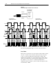
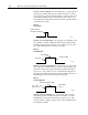
Phase A
Phase B
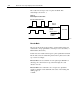
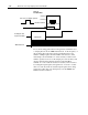
Encoder
Input A
Encoder
Input B
Very High Speed
Counter Module
Reverse Rotation
CW Encoder Rotation
Forward Rotation
CCW Encoder Rotation
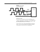
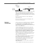
4µsec
min
1µsec
Typical
90
T
90
12
0
13
2
10679I
The following paragraphs apply to both encoders and counters.
Preset Value
Each of the 4 counters has one preset value associated with it. In the
encoder or counter modes, the preset value represents a reference
point (or count) from which the module begins counting. The
module can count either up or down from the preset value. Preset
values are loaded into the count registers through the preset count
bits. (Refer to word 1, bits 8-11 of the block transfer write
initialization block in chapter 5.) Preset values can range from 0 to
999,999 binary or BCD.