
User Manual

1–5
Overview of the Very High Speed Counter Module
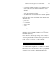
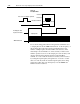
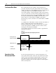
Figure 1.2
Block Diagram of Encoder Mode
From Encoder/Pulse Generator
Phase A
Terminal
Phase B
Terminal
(direction sense)
Gate/Reset
Terminal
1771VHSC
10678I
Direction of Count
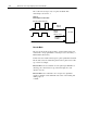
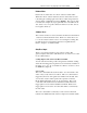
The module can count either up or down, depending upon the
condition of the B input for each counter. In encoder applications,
the counter will increment on the leading edge of Phase A, while
phase B determines the direction of the count.
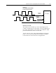
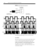
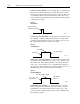
You also have the option of X1 and X4 multiplying of the input
pulses. 1.3 shows the relationships between phases A and B for
forward and reverse directions in encoder applications.