
User Manual

1–3
Overview of the Very High Speed Counter Module
• counter mode - channel B is tied high or low. Channel A input is
used for pulse. The count is unidirectional with the direction
determined by
channel B.
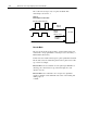
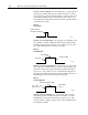
• encoder X1 - This is a bidirectional count mode; counting up or
down, using quadrature input signals.
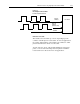
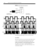
• encoder X4 - This is a bidirectional count mode, using quadrature
input signals, with 4 times the resolution of X1.
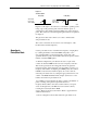
Each of the counters in encoder/counter mode has values associated
with it. These are:
• preset value
• rollover value
• gate/reset input
• output
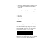
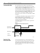
Counter Mode
The counter mode allows the module to read incoming pulses and
return them to the programmable controller processor as a binary or
BCD number (0-999,999).
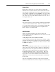
In the counter mode, direction (up counting or down counting) is
determined by the phase B input, which can be a random signal. If
Phase B is high, the counter will count down. If phase B is low or
floating, (that is, not connected), the counter counts up.
If Phase B is: Counter will count (direction):
High Down
Low or floating (not connected) Up
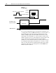
The module reads incoming pulses from a maximum of 4 encoders
(single-ended or differential), counters, pulse generators, mechanical
limit switches, and so forth and returns a count to the programmable
controller processor in a binary or BCD number (0-999,999).