Allen Bradley Very High Speed Counter Module (Cat. No.
Important User Information Because of the variety of uses for the products described in this publication, those responsible for the application and use of this control equipment must satisfy themselves that all necessary steps have been taken to assure that each application and use meets all performance and safety requirements, including any applicable laws, regulations, codes and standards. The illustrations, charts, sample programs and layout examples shown in this guide are intended solely for example.
Summary of Changes Summary of Changes Summary of Changes This release of the publication contains new and updated information from the last release. New Information This release includes information on the Series B version of the 1771-VHSC module. This includes a new Appendix E on the differences between period/rate and continuous/rate modes of operation. This information was not included in the previous version of this publication.
Table of Contents Summary of Changes . . . . . . . . . . . . . . . . . . . . . . . . SOC-1 Summary of Changes . . . . . . . . . . . . . . . . . . . . . . . . . . . . . New Information . . . . . . . . . . . . . . . . . . . . . . . . . . . . . . . . . Updated Information . . . . . . . . . . . . . . . . . . . . . . . . . . . . . . Change Bars . . . . . . . . . . . . . . . . . . . . . . . . . . . . . . . . . . . SOC-1 SOC-1 SOC-1 SOC-1 Using This Manual . . . . . . . . . . . . . . . . . . . . . . . . . . .
ii Table of Contents Installing the Very High Speed Counter Module . . . . . . . . . 2-1 Chapter Objectives . . . . . . . . . . . . . . . . . . . . . . . . . . . . . . . . . . . European Union Directive Compliance . . . . . . . . . . . . . . . . . . . . . EMC Directive . . . . . . . . . . . . . . . . . . . . . . . . . . . . . . . . . . . . Low Voltage Directive . . . . . . . . . . . . . . . . . . . . . . . . . . . . . . . Electrostatic Damage . . . . . . . . . . . . . . . . . . . . . . . . . . . . . . .
Table of Contents iii Troubleshooting . . . . . . . . . . . . . . . . . . . . . . . . . . . . . . . . 6-1 Chapter Objectives . . . . . . . . . . . . . . . . . . . . . . . . . . . . . . . . . . . Using the Indicators for Troubleshooting . . . . . . . . . . . . . . . . . . . . Troubleshooting Chart . . . . . . . . . . . . . . . . . . . . . . . . . . . . . . Diagnostic Codes Returned by the Module . . . . . . . . . . . . . . . . . . Diagnostics Reported in Word 1 of BTR . . . . . . . . . . . . . . . . . .
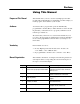
Preface Using This Manual Purpose of This Manual Audience This manual shows you how to use the Very High Speed Counter module with an Allen-Bradley programmable controller. It helps you install, program, and troubleshoot your module. You must be able to program and operate an Allen-Bradley programmable controller (PLC) to make efficient use of this module. In particular, you must know how to program your PLC for block transfer-type instructions. We assume that you know how to do this in this manual.
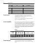
P–2 Using This Manual Chapter Title Topics Covered Appendices A Specifications Specifications for the VHSC module. B Sample Programs Sample programs for various PLC programs. C Application Considerations Selection of input devices and circuit descriptions. D Questions and Answers Helpful answers to the most asked questions.
Chapter 1 Overview of the Very High Speed Counter Module Chapter Objectives This chapter gives you information on: • features of the VHSC module • how the module communicates with programmable controllers. • how the module operates Module Description The VHSC module performs high speed counting for industrial applications. The module is an intelligent block transfer I/O module that interfaces signals with any Allen-Bradley programmable controller that has block transfer capability.
1–2 Overview of the Very High Speed Counter Module • returns in status either count or frequency in binary or BCD format • input counts as high as 999,999 • up to 500KHz in period/rate or rate measurement frequency modes • outputs can be tied to any counter • each output has a user-selectable on-off value • outputs can be tied back to an input for cascading • automatic default configuration • each counter has a user-selectable preset and rollover value • period/rate w/periodic outputs and period/rate w/dy
Overview of the Very High Speed Counter Module 1–3 • counter mode - channel B is tied high or low. Channel A input is used for pulse. The count is unidirectional with the direction determined by channel B. • encoder X1 - This is a bidirectional count mode; counting up or down, using quadrature input signals. • encoder X4 - This is a bidirectional count mode, using quadrature input signals, with 4 times the resolution of X1. Each of the counters in encoder/counter mode has values associated with it.
1–4 Overview of the Very High Speed Counter Module The counter mode accepts only one phase feedback. This relationship is shown in 1.1. Figure 1.1 Block Diagram of Counter Mode From Encoder/Pulse Generator Phase A Terminal Phase B Terminal (direction sense) 1771 VHSC Gate/Reset Terminal 10677 I Encoder Mode The encoder mode allows the module to read incoming pulses and return them to the programmable controller processor as a binary or BCD number (0-999,999).
Overview of the Very High Speed Counter Module 1–5 Figure 1.2 Block Diagram of Encoder Mode From Encoder/Pulse Generator Phase A Terminal 1771 VHSC Phase B Terminal (direction sense) Gate/Reset Terminal 10678 I Direction of Count The module can count either up or down, depending upon the condition of the B input for each counter. In encoder applications, the counter will increment on the leading edge of Phase A, while phase B determines the direction of the count.
1–6 Overview of the Very High Speed Counter Module Figure 1.
Overview of the Very High Speed Counter Module 1–7 Rollover Value Each of the 4 counters has one rollover value associated with it. When the rollover value is reached by the encoder/counter, it resets to 0 and begins counting again. The rollover values range from 0 to 999,999 binary or BCD (0 represents 1,000,000). The rollover value is circular (for example: if you program 360, the count will be from 358, 359, 0, 1 etc. in a positive direction and from 1, 0, 359, 358 etc. in a negative direction).
1–8 Overview of the Very High Speed Counter Module In mode 1, store/continue (1.4), the leading edge of a pulse input on the gate/reset terminal will cause the current value in the counter to be read and stored. The counter will continue counting. The stored count will be available in the block transfer read file. The stored count information will remain in the block transfer read file until it is overwritten by new data. Figure 1.4 Store/Continue Read, Store Count and continue counting.
Overview of the Very High Speed Counter Module 1–9 Figure 1.7 Store Reset/Start Rising Edge Store Count, reset to zero, start counting. Falling Edge Store Count, reset to zero, start counting. 10683 I Figures 1.4 through 1.7 show the store count feature operating on the rising edge of the gate/reset pulse. The user has the option of selecting these same features using the falling edge of the gate/reset pulse. This selection is made through the gate invert bit as explained in chapter 4.
1–10 Overview of the Very High Speed Counter Module Figure 1.8 Period/Rate Mode A Not used From user's encoder/pulse generator 1771 VHSC B Not used Gate/Reset Terminal From internal 4MHz clock scaler Incoming pulse train at gate/reset terminal Sampled pulses 4MHz internal clock 10684 I In 1.8, the incoming pulse train from the gate/reset terminal is used to sample pulses from the 4 MHz internal clock.
Overview of the Very High Speed Counter Module 1–11 Table 1.
1–12 Overview of the Very High Speed Counter Module Continuous/Rate Mode The continuous/rate mode is similar to the period/rate mode previously described except the outputs in this mode are dynamic outputs. Use this mode to determine the frequency of input pulses by counting the number of internal 4MHz clock pulses over a user-specified number of input signal pulses. Each output is turned on as soon as the turn-on count is reached, and turned off as soon as the turn-off count is reached.
Overview of the Very High Speed Counter Module 1–13 The value representing the sampled number of pulses is returned in BTR words 3 thru 10, and the value indicating the incoming frequency is returned in words 11-18. The total count equals the number of pulses received during the sample period. The operation of rate measurement mode is shown below in 1.10. Figure 1.
1–14 Overview of the Very High Speed Counter Module Sample Period You can set the sample period used in the frequency calculation in the rate measurement mode. Allowable values are 10 milliseconds to 2 seconds in 10 millisecond increments. The default value is 1 second. (Note: A 0 in the BTW initialization word is equivalent to the default value of 1 second.) The sample period is set in words 21 through 24 of the BTW initialization file (chapter 4).
Overview of the Very High Speed Counter Module 1–15 Operation of Outputs When the outputs for the VHSC module are enabled and assigned to a counter they operate in an ON-OFF fashion. For example, assume that the module were programmed to turn ON an output when a count value of 2000 was reached. Further, assume that the user desired to have the output remain energized for a period of 3000 counts and then turn OFF.
1–16 Overview of the Very High Speed Counter Module Tying Outputs to Counters You can jumper any of the outputs to any of the counter inputs on the module field wiring arm. In this way, it is possible to use the outputs to reset a counter or to cascade counters. If using the outputs this way, make certain that the input voltage jumpers are set to interface with the appropriate output voltage. Handshaking A pair of handshaking bits are provided for each counter.
Overview of the Very High Speed Counter Module 1–17 The default mode for the VHSC module is the counter mode for all 4 of the counters. In the default configuration, the module will continuously return counts (0-999,999 binary) to the programmable controller processor. The presets and rollovers associated with each of the 4 counters will not be active, nor will any of the outputs be active.
1–18 Overview of the Very High Speed Counter Module 6. Your ladder program can use/or move the data (if valid) before it is written over by the transfer of new data in a subsequent transfer. Chapter Summary In this chapter you learned how your module operates, and how your module communicates with the programmable controller.
Chapter 2 Installing the Very High Speed Counter Module Chapter Objectives This chapter gives you information on: • • • • • calculating the chassis power requirement keying a chassis slot for your module setting the voltage and filter jumpers wiring the input module’s field wiring arm installing the input module Before installing your module in the I/O chassis you must: Before You Install Your Module Action required: Refer to: Calculate the power requirements of all modules in each chassis.
2–2 Installing the Very High-Speed Counter Module • Industrial Automation Wiring and Grounding Guidelines, publication 1770-4.1 • Guidelines for Handling Lithium Batteries, publication AG-5.4 • Automation Systems Catalog, publication B111 Electrostatic Damage Electrostatic discharge can damage semiconductor devices inside this module if you touch backplane connector pins.
Installing the Very High-Speed Counter Module Module Keying 2–3 Use the plastic keying bands, shipped with each I/O chassis, for keying the I/O slot to accept only this type of module. The module is slotted in two places on the rear edge of the circuit board. The position of the keying bands on the backplane connector must correspond to these slots to allow insertion of the module.
2–4 Installing the Very High-Speed Counter Module Setting the Configuration Jumpers The VHSC module has user-selectable jumpers for each input channel.
Installing the Very High-Speed Counter Module 2–5 Figure 2.2 Setting the Configuration Jumpers Filter Jumper Position Voltage Jumper Position Down Down Down Up Up Down Up Up Description of Operation 12 24V High Speed (factory default setting) 5V High Speed 12 24V with low speed filter 5V with low speed filter * FILTER HI SPEED 5V 12 24V A0 B0 G0 10688 I *In the filter position, the module will not see frequencies above 100Hz. 3.
2–6 Installing the Very High-Speed Counter Module Figure 2.3 Connection Diagram for Very High Speed Counter Module (1771 VHSC) (See applicable codes and laws.
Installing the Very High-Speed Counter Module 2–7 Figure 2.4 Cable Grounding Ground Shield at I/O chassis mounting bolt Shield and drain twisted into single strand Field Wiring Arm 17798 Refer to Wiring and Grounding Guidelines, publication 1770-4.1 for additional information. Installing the Module When installing your module in an I/O chassis: 1.
2–8 Installing the Very High-Speed Counter Module 4. Snap the chassis latch over the top of the module to secure it. 5. Connect the wiring arm to the module. Interpreting the Indicator Lights The front panel of the input module contains 12 input indicators, 8 output indicators, an active indicator and a fault indicator (Figure 2.5). At power-up, the active and fault indicators are on. An initial module self-check occurs. If there is no fault, the red indicator turns off.
Chapter 3 Module Programming Chapter Objectives In this chapter we describe: block transfer programming sample programs in the PLC-2, PLC-3 and PLC-5 processors Block Transfer Programming Your module communicates with the processor through bidirectional block transfers. This is the sequential operation of both read and write block transfer instructions. The following example programs accomplish this handshaking routine.
3–2 Module Programming PLC 2 Program Example Figure 3.1 below shows a sample PLC-2 program. Figure 3.1 PLC 2 Family Sample Program Structure The VHSC module is located in rack 1, module group 0, slot 0. The data address 030 is among the first available timer/counters used for block transfer. The default block length of 0 results in a 18 word block transfer read. The module status data is returned to the processor starting at address 301.
Module Programming PLC 3 Program Example 3–3 Block transfer instructions with the PLC-3 processor use one binary file in a data table section for module location and other related data. This is the block transfer control file. The block transfer data file stores data that you want transferred to the module (when programming a block transfer write) or from the module (when programming a block transfer read). The address of the block transfer data files are stored in the block transfer control file.
3–4 Module Programming PLC 5 Program Example Block transfer instructions with the PLC-5 processor use one binary file in a data table section for module location and other related data. This is the block transfer control file. The block transfer data file stores data that you want transferred to the module (when programming a block transfer write) or from the module (when programming a block transfer read). The address of the block transfer data files are stored in the block transfer control file.
Module Programming PLC 5/250 Program Example 3–5 Block transfer instructions with the PLC-5/250 processor use one binary file in a data table section for module location and other related data. This is the block transfer control file. The block transfer data file stores data that you want transferred to the module (when programming a block transfer write) or from the module (when programming a block transfer read).
Chapter 4 Configuring Your Module Chapter Objectives Configuring the VHSC Module In this chapter you will read how to configure your module’s hardware, condition your inputs and enter your data. You must configure your module to conform to the input device and specific application that you have chosen. Data is conditioned through a group of data table words that are transferred to the module using a block transfer write (BTW) instruction.
4–2 Configuring Your Module Configuration Block for a Block Transfer Write The complete configuration block for the block transfer write to the module is defined in Table 4.A below. Table 4.
Configuring Your Module Word 15 14 13 12 11 10 09 34 08 07 06 05 04 03 02 4–3 01 00 Output 1 Off LSD Words repeat for each additional output: 35 39 output 2, 40 44 output 3, 45 49 output 4, 50 54 output 5, 55 59 output 6 60 Not used Tie Output 7 to Counter 61 Output 7 On MSD 62 Output 7 On LSD 63 Output 7 Off MSD 64 Output 7 Off LSD Bit/Word Descriptions Bit/word descriptions of BTW file words are presented in Table 4.B.
4–4 Configuring Your Module Word Bits Word 3 bits 00 02 Description Determine rate measurement mode, encoder mode, counter mode or period/rate mode for COUNTER 0.
Configuring Your Module Word Word 4 Bits 4–5 Description bit 15 Invert signal bit for gate/reset terminal. 0 = Not inverted 1 = Inverted bits 00 02 Determine rate measurement mode, encoder mode, counter mode or period/rate mode for COUNTER 2.
4–6 Configuring Your Module Word Bits Description Mode 4 (store reset/start) used bit 15 1 0 0 Invert signal bit for gate/reset terminal. 0 = Not inverted 1 = Inverted Words 5 thru 12 Rollover value. When rollover value is reached, the counter value becomes 000,000 and counting continues from that point. The range for both MSD and LSD is 0 to 999. Word 5 Rollover value. Most significant digit for counter 0. Word 6 Rollover value. Least significant digit for counter 0. Word 7 Rollover value.
Configuring Your Module Word Chapter Summary Bits 4–7 Description Words 35 thru 39 These words are a repeat of words 25 through 29 with the exception of the output number. These words are for output 2. Words 40 thru 44 These words are a repeat of words 25 through 29 with the exception of the output number. These words are for output 3. Words 45 thru 49 These words are a repeat of words 25 through 29 with the exception of the output number. These words are for output 4.
Chapter 5 Module Status and Input Data Chapter Objectives In this chapter you will read about: • reading data from your module • module read block transfer format Reading Data from the Module Block transfer read (BTR) programming moves status and data from the input module to the processor’s data table (Table 5.A). The processor user program initiates the request to transfer data from the module to the processor.
5–2 Module Status and Input Data (Octal Bit) 17 16 15 14 13 12 11 10 07 06 05 04 03 02 01 00 Decimal Bit 15 14 13 12 11 10 09 08 07 06 05 04 03 02 01 00 13 Counter 1 Store count values MSD (range 0 999) in encoder/counter mode; or frequency value MSD (range 0 500) in rate measurement or period/rate mode 14 Counter 1 Store count values LSD (range 0 999) 15 Counter 2 Store count values MSD (range 0 999) in encoder/counter mode; or frequency value MSD (range 0 500) in r
Module Status and Input Data Bit/Word Description for Block Transfer Read Table 5.B provides bit/word descriptions for the block transfer read instruction returned by the 1771-VHSC module to the processor. Table 5.B Bit/Word Description for the VHSC Module (1771 VHSC) Word Word 1 Word 2 5–3 Bit Definition Bit 00 Power up bit indicates whether a successful BTW with valid data has occurred since powerup, or since last switched from Program to Run mode.
5–4 Module Status and Input Data Word Chapter Summary Bit Definition Words 12 Counter 0 Store count values LSD (range 0 999) Words 13 Counter 1 Store count values MSD (range 0 999) in encoder/counter mode; or frequency value MSD (range 0 500) in rate measurement or period/rate mode Words 14 Counter 1 Store count values LSD (range 0 999) Words 15 Counter 2 Store count values MSD (range 0 999) in encoder/counter mode; or frequency value MSD (range 0 500) in rate measurement or period/rate mode W
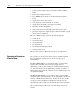
Chapter 6 Troubleshooting Chapter Objectives In this chapter you will learn how to troubleshoot your VHSC module using the indicators on the front of the module, and the troubleshooting flowchart. Using the Indicators for Troubleshooting The indicators on the front of the module are an aid in troubleshooting.
6–2 Troubleshooting Diagnostic Codes Returned by the Module The VHSC module returns diagnostics in word 1 of the block transfer read (BTR) to the processor. These codes are identified below. Diagnostics Reported in Word 1 of BTR Word 1 Bit Indication Power up bit indicates whether a successful BTW with valid data has occurred since power up, or since last switched from Program to Run mode.
Appendix Specifications Number of Counters Module Location Maximum Count Value BTW Processing Time (worst case) Maximum Input Frequency Inputs per Counter Input Voltage Input Current Minimum Input Current Number of Outputs Maximum Output Off state Leakage Current Maximum On state Voltage Drop Output Control Output Voltage Output Current Output Switching Time Filtering Backplane Current Output Conductors Wire Size Category Length Wire Size Category Fuse Environmental Conditions less than 10µA @ 24V dc
B Appendix Sample Programs Sample Program for PLC-2 Family Processors These rungs illustrate a method of monitoring the count for values greater than 3 digits. The total count is displayed in words 333 and 334. This rung set storage bit 405/1 when the count is between the MSD lower limit and the MSD upper limit.
B–2 Sample Programs Sample Program for PLC-5 Family Processors This rung illustrates how to assemble the count MSD and LSD into one floating point word that can be used throughout the program. F23:0 is an intermediate storage value and F23:1 contains the total count 0 value. Total count = (MSD * 1000) + LSD, [F23:1 = (N22:103 * 1000) + N22:104] N22:103 is count 0 MSD F23:0 = (1000 * count 0) VHSC BTR Done Bit N21:0 MUL MULTIPLY SOURCE A SOURCE B 1 13 DEST ADD ADD SOURCE A SOURCE B DEST N22:103 1000.
Sample Programs (FROM PREVIOUS PAGE) B–3 (FROM PREVIOUS PAGE) N22:13 = COUNT 0 PRESET MSD MOV MOVE SOURCE A N24:0 2 DEST N22:13 2 FLT POINT STORE WORD MUL MULTIPLY SOURCE A SOURCE B DEST N22:13 2 1000.000 F23:4 2000.000 N22:14 = COUNT 0 PRESET LSD SUB SUBTRACT SOURCE A SOURCE B DEST F23:2 2.789000 F23:4 2000.
B–4 Sample Programs Addditional Sample Program for PLC-5 Family Processors This block transfer read rung can be used alone or with the block transfer write rung shown below. If used alone, all VHSC counters will operate in a default mode of outputs disabled, rollover at 999,999 and count mode with pulses counted on channel A, direction sensed at channel B and the gate is not active.
Appendix C Application Considerations Appendix Objectives Types of Input Devices This appendix will provide you with background for selecting the appropriate input device for your 1771-VHSC module, explain the output circuit, and provide you with information for selecting the type and length of input cabling. To turn on an input circuit in the VHSC module, you must source current through the input resistors sufficient to turn on the opto-isolator in the circuit.
C–2 Application Considerations Circuit Overview To make sure your signal source and the 1771-VHSC module are compatibility, you need to understand the electrical characteristics of your output driver and its interaction with the 1771-VHSC input circuit. Refer to Figure C.1. The most basic circuit would consist of R1, R2, JPR4, JPR5, the photodiode and associated circuitry around half of the opto-isolator.
Application Considerations C–3 The optical isolator manufacturer recommends a maximum of 8mA to flow through the photodiode. This current could be exceeded in the 24V position. To obtain this limit, a dc shunt circuit is included, consisting of D1, Q2, R97 and R98. If the photodiode current exceeds about 8mA, the drop across R97-R98 will be sufficient to turn Q2 on, and any excess current will be shunted through D1 and Q2 instead of through the photodiode.
C–4 Application Considerations 5V Differential Line Driver Example You want to use a 5V differential line driver in your encoder when you have a long cable run and/or high input frequency or narrow input pulses (input duty cycle < 50%). The top circuit (NO TAG) shows a typical 5V differential line driver. The output is connected to the field wiring arm terminal 1 and is sourcing current and the output to terminal 2 is sinking current. JPR5 is connected to short out resistor R1.
Application Considerations C–5 +12 to +24V Single Ended Driver Some European-made encoders use a circuit similar to the lower circuit in Figure C.2. The current capable of being sourced is limited only by the 22 ohm resistor in the driver output circuit (R). If a 24 volt supply is used, and this driver supplies 15mA, the output voltage would still be about 23V (15mA x 22 ohms = 0.33V, and Vce = .7V). Figure C.
C–6 Application Considerations Open Collector Open collector circuits (the upper circuit in Figure C.3) require close attention so that the input voltage is sufficient to produce the necessary source current, since it is limited not only by the 1771-VHSC input resistors but also the open collector pull-up. Jumper position provides some options as shown in the table below. Supply Voltage verses Jumper Settings Supply Voltage Jumper Setting Total Impedance Available Current +12 JPR4 3.15K 3.
Application Considerations C–7 Electromechanical Limit Switch When using an electromechanical limit switch (the lower circuit in Figure C.3), you must connect the low speed limit capacitor (C4) using jumper JPR11. The RC time constant of R31 and C4 will filter out switch contact bounce. However, this limits the frequency response to around 100Hz. This circuit would be similar when using dc proximity switches, but bounce should not occur unless severe mechanical vibration is present.
C–8 Application Considerations Application Considerations A successful installation depends on the type of input driver, input cable length, input cable impedance, input cable capacitance, frequency of the input. The following provides information on these installation factors for the 1771-VHSC module. Input Cable Length Maximum input cable length depends on the type of output driver in your encoder, the kind of cable used, and maximum frequency at which you will be running.
Application Considerations C–9 Cable Impedance Generally, you want the cable imedance to match the source and/or load as closely as possible. Using 150 ohm Belden 9182 (or equivalent) cable more closely matches the impedance of both encoder and module input circuits than 78 ohm cable, such as Belden 9463. A closer impedance match minimizes reflections at high frequencies.
Appendix D Questions and Answers General Questions and Answers This appendix presents some of the more commonly asked questions about application and operation of the Very High Speed Counter module. The following questions and answers do not cover all possible questions, but are representative of the more common ones. Q. If I do not connect channel B in counter mode, what happens to the count status? A. With channel B disconnected or tied low, the module will count up only.
D–2 Questions and Answers Q. What does it mean when an output indicator is on? A. Since the output indicator is tied to the control side of the module, it means that the module has commanded the output on. It does not necessarily mean that the output is on. The indicator illuminates even when no connection is made to the outputs or to the output supply. For an output to actually turn on, the output supply must be connected. Q. What are the delay times for turning the outputs on and off? A.
Questions and Answers A. D–3 In rate measurement, you select a time period in BTW words 21-24. The module will count pulses on channel A for this time period, and then convert the number to frequency. It will begin its next time period in about 10msec, and then begin counting pulses again. In period/rate or continuous/rate modes, the pulses coming in on the gate/reset will gate the internal 4MHz clock using the hardware scaler selected in words 21-24.
D–4 Questions and Answers Q. How do my output on-off values work? A. The first value is always the on value, and the second value is always the off value. For example, with a rollover value of 2000, if I specify an on value of 1999 and an off value of 0, the output will only be on when the count equals 1999. If I specify an on value of 0 and an off value of 1999, the output will only be off at a count of 1999. Q. How do my outputs work if I tie them to an input used in frequency mode. A.
Questions and Answers D–5 Q. What happens if I change my BTW length after power up to save block transfer time? A. As long as the length is valid, the module will retain the data previously sent to it as long as backplane power to the module is present. If you power up with a block transfer length of 64 words to configure the module, and later change to 2 words, the module will behave in the manner prescribed in the 64 word transfer. It will do this until you power down, and power back up.
Appendix E Period/Rate and Continuous/Rate Examples General The totalizer is always active in period/rate and continuous rate modes. To access the values, the BTR length must be changed to a value between 20 and 26 in multiples of 2. A length of 20 will return the total count for C0, a length of 22 will return the total count for C1 and C0, and so on. A BTR length of 0 will still return 18 words. The reset bits will now reset the total count in words 19-26.
E–2 Period/Rate and Continuous/Rate Examples When doing BTWs whose length is greater than 3 or if the BTW data changes, the potential to miss pulses is limited to (number of pulses in 6ms – scaler) every time there is a transition of BTW data if the number pulses that occur in 6ms is greater than scaler. If the number of pulses that occur in 6ms is less than the scaler, the count will remain accurate.
Period/Rate and Continuous/Rate Examples Operation of Outputs in Period/rate Mode (1771 VHSC Revision B Modules) E–3 The following examples demonstrate the operation of the outputs in period/rate mode of operation for the 1771-VHSC revision B modules. 1. If scaler = 1 The 4MHz count, frequency, new data bit, totalized count and outputs will be updated on the trailing edge of every pulse at the gate/reset input. 2.
E–4 Period/Rate and Continuous/Rate Examples Note: “Left over” pulses are pulses that occur that are not divisible by the scaler. (i.e. With a scaler of 4, if 6 pulses occur there are 2 “left over” pulses.) Operation of Outputs in Continuous/Rate Mode The following example demonstrates the operation of the outputs in Continuous/Rate mode of operation. Note that Y = time between incoming pulses trailing edge to leading edge, A = output on value, and B = output off value.
Period/Rate and Continuous/Rate Examples E–5 The 4MHz count, total count, frequency and new data bit reported to the programmable controller will be updated every scaler number of pulses. And 250–260ms after the last pulses stop, the 4MHz count will go to 999,999, the frequency will go to 0 and the new data bit will be set. The outputs are updated dynamically on the module as the 4MHz count increases.
E–6 Period/Rate and Continuous/Rate Examples Figure E.2 Operation of Outputs in Period/Rate and Continuous/Rate with Scaler = 2 50Hz at Gate/Reset 50% Duty Cycle Scaler = 2 What the counter sees internally with scaler = 2. Counter Idle Counter times width of pulse 4MHz count = 80,000 CHANNEL IN PERIOD/RATE 4MHz Count = 80,000 Scaler = 2 ON at 20,000 OFF at 80,000 CHANNEL IN CONTINUOUS/RATE 4MHz Count = 80,000 4MHz Count = 20,000 Scaler = 2 ON at 20,000 OFF at 80,000 12633-I Figure E.
Index Symbols E **Empty**, P-1, P-2, C-1, C-7, C-8 electrostatic discharge, EMC directive, 2-1 encoder, phase relationship, 1-6 A encoder mode block diagram, 1-4 direction of count, 1-5 operation, 1-2 application considerations, C-8 B bit/Word descriptions, block transfer read bit/word descriptions, programming, 5-1 encoder X4, 1-3 4-3 G 5-3 gate reset input, 1-7 BTR, 3-1 bit/word description, 5-3 word assignments, 5-1 grounding, 2-6 H BTR length, E-1 BTW, 3-1 bit/word descriptions, 4-3 c
I–2 Index M rate measurement mode, revision B changes, E-2 module description, 1-1 module features, module location, rollover value, 1-1 module installation, 1-12 2-7 1-7 S 2-2 sample period, 1-14 O sample program, PLC-2, sample programs PLC-2, B-1 PLC-5, B-2, B-4 operation of outputs continuous/rate mode, E-4 period/rate mode, E-3 scaler in period/rate and continuous/rate modes, E-1 operation, 1-11 output circuit, C-7 circuit diagram, C-7 outputs assigning to counters, 1-14 enabling and f
Allen Bradley, a Rockwell Automation Business, has been helping its customers improve productivity and quality for more than 90 years. We design, manufacture and support a broad range of automation products worldwide. They include logic processors, power and motion control devices, operator interfaces, sensors and a variety of software. Rockwell is one of the world's leading technology companies. Worldwide representation.