
Manual

1–6
Interfacing with the Temperature Control Module
Publication
17716.4.5 - January 1997
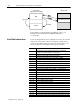
The configuration software uses word 0 to control the
communications between the PLC processor and the module. Bits 0
through 11 of word 0 of the data-table interface area are
communication control bits. Based on your input to the Temperature
Control software, bits 0 through 11 will be used to initiate a
corresponding block-transfer. Your ladder logic program must
respond to this input by generating the required block-transfer. Bits
14 and 15 are used internal to the example program.
Word
Offset
Bit Description
0
0 Loop1 configuration block write to TCM required
1 Loop2 configuration block write to TCM required
2 Loop3 configuration block write to TCM required
3 Loop4 configuration block write to TCM required
4 Loop5 configuration block write to TCM required
5 Loop6 configuration block write to TCM required
6 Loop7 configuration block write to TCM required
7 Loop8 configuration block write to TCM required
8 Autotune (system ID data) block write to TCM required
9 Autotune (system ID data) block read from TCM required
10 Gains block write to TCM required
11 Gains block read from TCM required
12 not used
13 not used
14 Used by the example ladder logic as:
A manual download requested but no blocktransfer in progress
15 Used by the example ladder logic as:
Blocktransfer to/from TCM in progress
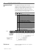
0123456789101112131415
Loop 1
Loop 2
Loop 3
Loop 4
Loop 5
Loop 6
Loop 7
Loop 8
Write configuration block
Write gains block
Read gains block
Write autotune block
Read autotune block
Word N7:0
Initiate a blocktransfer with
one of these 12
communication control bits
Do not control these 2
bits with your ladder
logic outside of this
example program
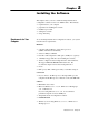
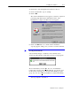
To learn how to install the Temperature Control configuration
software, read chapter 2
Communication Control
Bits
What to do next