
Manual

1–4
Interfacing with the Temperature Control Module
Publication
17716.4.5 - January 1997
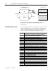
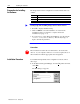
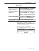
Download
Computer with
Temperature Control Software
DataTable Interface Area
PLC Data Table
RAM
Disk Files
Upload
For information on block-transfer programming, refer to your
Temperature Control Module User Manual (publication
1771-6.5.120)
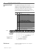
To use the Temperature Control configuration software, the read and
write blocks, along with a control word, must be organized into a
614-word data-table interface area in an integer file with the word
offsets shown below. The utility ladder logic provides this.
Word Offset Description
0 Communication control word (initiates blocktransfer of configuration
autotune, or gains values when you set a specific bit)
1 Used by the example ladder logic as: BT identity bits
2 Used by the example ladder logic as: BT check mask
3 Used by the example ladder logic as: Cycle sequence number
4 Used by the example ladder logic as: Loop offset value
5 Used by the example ladder logic as: Datatable file offset
6 Not used by the example ladder logic
7 Not used by the example ladder logic
8 Not used by the example ladder logic
9 Used by the example ladder logic as: TPO bits singletransferred
10 - 39 Loop1 configuration block (26 words)
40 - 69 Loop2 configuration block (26 words)
70 - 99 Loop3 configuration block (26 words)
100 - 129 Loop4 configuration block (26 words)
130 - 159 Loop5 configuration block (26 words)
160 - 189 Loop6 configuration block (26 words)
190 - 219 Loop7 configuration block (26 words)
220 - 249 Loop8 configuration block (26 words)
250 - 309 Gains block (57 words)
310 - 349 Dynamic block (34 words)
350 - 419 Status block (64 words)
420 - 479 Autotune block (system ID data) (57 words)
480 - 549 Scratchpad area addressed by the blocktransfer write instruction (64 words)
550 - 613 Scratchpad area addressed by the blocktransfer read instruction (64 words)
DataTable Interface Area