
Manual

1–3
Interfacing with the Temperature Control Module
Publication
17716.4.5 - January 1997
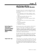
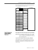
The following graphic illustrates how the individual data blocks are
sent to and returned from the TCM module.
Configuration Block for Loop 2
26 words
Configuration Block for Loop 1
26 words
Configuration Block for Loop 3
26 words
Configuration Block for Loop 4
26 words
Configuration Block for Loop 5
26 words
Configuration Block for Loop 6
26 words
Configuration Block for Loop 7
26 words
Configuration Block for Loop 8
26 words
Gains Block
57 words
System Status Block
64 words
Calibration Write Block
20 words
AutoTune Block
57 words
1771TCM ModulePLC Data Table
Input Byte
BlockTransfer
BlockTransfer
BlockTransfer
BlockTransfer
BlockTransfer
BlockTransfer
BlockTransfer
BlockTransfer
BlockTransfer
BlockTransfer
BlockTransfer
BlockTransfer
Calibration Read Block
14 words
BlockTransfer
Output Byte
Dynamic Block
34 words
BlockTransfer
SingleTransfer
SingleTransfer
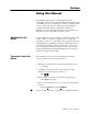
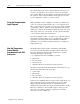
The computer with the Temperature Control software communicates
with the PLC processor across a local DH+ link or a DF1 serial link.
Important: For configuring temperature control loops, you can not
have the computer on one DH+ link and have the PLC
processor on another (remote) DH+ link even if they are
in the same DH+ network.
As shown in the following graphic, after entering configuration
selections at the computer, you can download them to disk files
and/or the PLC processor’s data-table interface area for use by the
module. Later, you can upload configuration selections from either
the disk files or the PLC processor’s data-table interface area for
making changes.
How the Temperature
Control Software
Interfaces with PLC
Processors