
Manual

Chapter
8
8-1
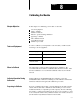
Calibrating the Module
In this chapter, for calibrating your module, we describe:
tools and equipment
when to calibrate
calibration methods
indicator operation during calibration
preparing to calibrate
write calibration block
read calibration block
calibration procedure
In order to calibrate your temperature control module you will need the
following tools and equipment:
Tool or Equipment Description
Precision Voltage Source
0-10V, 1µV resolution
Precision Multimeter
10V, 1µV resolution
Industrial Terminal and
Interconnect Cable
Programming terminal for PLC processors
The temperature control module is shipped factory calibrated. We
recommend that the module be recalibrated after the first 6 months. After
the first recalibration, we recommend recalibration after each 12-month
interval.
During calibration, the RUN/FLT indicator will turn to green; the
CAL/COM indicator will turn to flashing red. The indicators will remain
with these indications throughout the calibration procedure.
If need to recalibrate the module, you must calibrate the module in an I/O
chassis. The module must communicate with the PLC processor and an
industrial terminal (or compatible personal computer). Before calibrating
the module, you must enter ladder logic into the processor memory, so that
it can send (block-transfer write) calibration data to the module, and access
(block-transfer read) calibration data from the module.
Chapter
Objective
Tools and Equipment
When to Calibrate
Indicator Operation During
Calibration
Preparing to Calibrate