
Manual


Chapter 6
Operating the Module
6-7
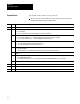
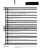
Word DescriptionBits
30
0 Loop8 Enable
•0 = Loop 8 disabled.
•1 = Loop 8 enabled if PID control mode selected (bits 7-8, word 2, config block).
1 Loop8 Auto/Manual Mode Select
•0 = Loop 8 is in the manual mode the manual output value (from word 33) is used as the CV value.
•1 = Loop 8 is in the automatic mode the PID algorithm generates the CV value.
2 Loop8 SetPoint Select
•0 = Select the standbytemperature setpoint value from word 31.
•1 = Select the runtemperature setpoint value from word 32.
3 Loop8 AutoTuning Enable
•0 = Disable autotuning.
•1 = Enable autotuning autotuning can be invoked by an offtoon transition of bit 1 of word 34.
4 Always = 0.
5 Loop8 PID Integral Term Reset Enable
•0 = Accumulate PID integral term.
•1 = Reset the PID integral term on the 0to1 transition, and then allow accumulation until the next 0to1 transition.
6-15 Always = 0.
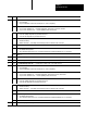
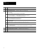
31 0-15
Loop8 Standby Temperature Setpoint Value Used when bit 2 of word 30 is off (0 thru 999.9
).
32 0-15
Loop8 Run Temperature Setpoint Value Used when bit 2 of word 30 is on (0 thru 999.9
).
33 0-15 Loop8 Manual Output Value (CV) Used when bit 1 of word 30 is off (-100.00 thru +100.00).
34
0 ReadBlock Select
•0 = Blocktransfer read will return the system status block.
•1 = Blocktransfer read will return the gains block.
1 Invoke AutoTuning
•0 = Stop autotuning.
•1 = Invoke autotuning of all loops with autotuning enable bit turned on. (start only on a 0to1 transition).
2 Always = 0.
3 ColdJunction Alarm Enable
•0 = Disable alarm for temperature over and under limits.
•1 = Enable alarm for temperature over the upper limit (70
C) and under the lower limit (0
C).
4 Celsius/Fahrenheit Select For all temperature values.
•0 = Celsius
•1 = Fahrenheit
5-15 Always = 0.30313233
To learn how to monitor the system status block of the temperature control
module, read chapter 7.
What to do next