
Manual

Configuring the Module
Chapter 4
4-4
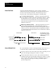
Word DescriptionBits
3
0 Always = 0.
1 Control Action
•0 = Control action is E = SP-PV
•1 = Control action is E = PV-SP
2-3 Always = 00.
4 CV Ramping Selects whether to use a fixed CV ramp rate (set in word 4) for PV to reach the set point.
•0 = Disable CV ramping.
•1 = Enable CV ramping.
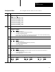
5-6 Cooling Method
bit 6 bit 5 selection
•0 0 = No cooling.
•0 1 = Air cooling.
•1 0 = Oil cooling.
•1 1 = Water cooling.
7 Alarm Enable
•0 = Suppress all alarms.
•1 = Report all alarm conditions.
8-9 AutoTuning Gains Selects gains to use during autotuning.
bit 9 bit 8 selection
•0 0 = Low gains.
•0 1 = Medium gains.
•1 0 = High gains.
•1 1 = Not used (illegal value).
10 Do/Don't Use AutoTuning Gains Selects gains to use after autotuning.
•0 = Use the gains derived from autotuning.
•1 = Use the gains blocktransferred to the module before autotuning.
11-15 Always = 0 0000.
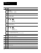
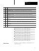
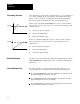
4 0-15 CV Ramp Rate If enabled by bit 4 of word 2, the maximum rate (degrees/minute) at which the CV is allowed to increase as the
PV reaches the setpoint. (0.00 thru 99.99)
5 0-15
Maximum PV in Engineering Units (0 thru 999.9
)
6 0-15
Minimum PV in Engineering Units (0 thru 999.9
)
7 0-15 High CV Limit The maximum CV percentage allowable. (-100.00 thru +100.00)
8 0-15 Low CV Limit The minimum CV percentage allowable. (-100.00 thru +100.00)
9 0-15 Forced CV Value on TC Break The percentage value forced into the CV when a broken TC is detected. (-100.00 thru +100.00)
10 0-15 Forced CV Value on Thermal Runaway The percentage value forced into the CV when thermal runaway is detected.
(-100.00 thru +100.00)
11 0-15 Heat Minimum Cycle Time The minimum cycle time in seconds for which the heat bit is on. (0.00 thru 100.00)
12 0-15 Heat Maximum Cycle Time The maximum cycle time in seconds for which the heat bit is on. (0.00 thru 100.00)