
Manual

Chapter 4
Configuring the Module
4-3
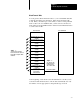
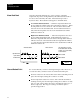
The configuration block contains 23 words as follows:
Word Bits Description
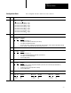
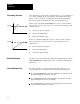
1 0-15 Block Identification Code
bit 15
. . . . . . . . . . . bit 0
•1000 1000 0000 0001 (8801
16
) = loop 1
•1000 1000 0000 0010 (8802
16
) = loop 2
•1000 1000 0000 0011 (8803
16
) = loop 3
•1000 1000 0000 0100 (8804
16
) = loop 4
•1000 1000 0000 0101 (8805
16
) = loop 5
•1000 1000 0000 0110 (8806
16
) = loop 6
•1000 1000 0000 0111 (8807
16
) = loop 7
•1000 1000 0000 1000 (8808
16
) = loop 8
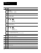
2
0 Always = 0.
1-2 TC Break Detection Configuration When a TC break is detected (if auto mode had been selected in the dynamic block), the
operating mode is switched to:
bit 2
bit 1 selection
•0 0 = Disable PID loop (CV = 0)
•0 1 = Set output to TCbreak forced CV value (set in word 9).
•1 0 = Set output to manualmode CV value.
•1 1 Do not use this selection. It will freeze the output at the current CV value. However, the CV value will have already
moved to beyond a satisfactory value before the TC break is detected.
3 Always = 0.
4-5 Thermal Runaway Configuration When a runaway condition is detected, the operating mode is set as:
bit 5 bit 4 selection
•0 0 = Disable PID loop (CV = 0)
•0 1 = Set output to thermalrunaway forced CV value (set in word 10).
•1 0 = Set output to manualmode CV value.
•1 1 is not used (illegal value).
6 Always = 0.
7-8 Loop Operational Mode
bit 8 bit 7 selection
•0 0 = Monitor TC input to indicate temperature and alarms, but no PID control of CV value (CV value held at 0).
•0 1 = Perform PID control of loop.
•1 0 = Disable loop (no CV value, temperature or alarms).
•1 1 is not used (illegal value).
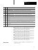
9-11 Always = 000.
12-15 Thermocouple Type
bit 15
. . 12 selection
• 0 0 0 0 = mV
• 0 0 0 1 = B
• 0 0 1 0 = E
bit 15 . . 12 selection
• 0 0 1 1 = J
• 0 1 0 0 = K
• 0 1 0 1 = R
bit 15
. . 12 selection
• 0 1 1 0 = S
• 0 1 1 1 = T
Configuration Block