
Manual

Communicating with Your Module
Chapter 3
3-6
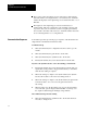
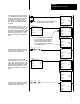
Controlling Heating and Cooling Elements
In applications where the control variable TPO of each loop is used for
both heating and cooling, the ladder logic for data single-transferred
to/from the 1771-TCM module must do the following:
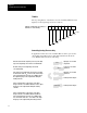
Write
the decimal value 35 (binary 00100011) to the high
byte of the output image word of the 1771TCM module.
Read the low byte of the input image word of the
1771TCM module.
If the low byte of the input image word of the 1771TCM
module has the value 35
10
, move the value from the high
byte of the input image word of the 1771TCM module to
the output image byte of the outputs driving the heating
elements.
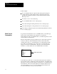
If bit 0 (watchdog timer) of the low byte of the input
image word of the 1771TCM module
off
, zero the output
image byte of the outputs driving the heating elements
and zero the output image byte of the outputs driving the
cooling elements.
If bit 0 (watchdog timer) of the low byte of the input
image word of the 1771TCM module
on
and the low
byte of the input image word of the 1771TCM module
does not have the value 35
10
or 37
10
, do not write to the
output image byte of the outputs driving the heating
elements.
High byte of 1771TCM
output word
Low byte of 1771TCM
input word
High byte of 1771TCM
input word
Heatingelement outputs
Heatingelement outputs
35
10
?
35
10
00000000
2
W
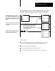
rite the decimal value 37 (binary 00100101) to the high
byte of the output image word of the 1771TCM module.
Read the low byte of the input image word of the
1771TCM module.
If the low byte of the input image word of the 1771TCM
module has the value 37
10
, move the value from the high
byte of the input image word of the 1771TCM module to
the output image byte of the outputs driving the cooling
elements.
High byte of 1771TCM
output word
Low byte of 1771TCM
input word
High byte of 1771TCM
input word
Coolingelement outputs
37
10
?
37
10
Coolingelement outputs
00000000
2
W
rite the decimal value 35 (binary 00100011) to the high
byte of the output image word of the 1771TCM module.
High byte of 1771TCM
output word
35
10
Loop back to step 2.
Step 2
Step 3
Step 4
Step 5
Step 6
Step 7
Step 8
Step 9
Step 10
Step 1
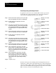
The key to this logic is the switching between reading the heat bits and
reading the cool bits from the same input image byte. The following figure
shows an example of PLC-5 ladder logic to handle data single-transferred
to/from the 1771-TCM module in an application where the control variable
TPO of each loop is used for both heating and cooling.