Temperature Control Module (Cat. No.
Important User Information Because of the variety of uses for the products described in this publication, those responsible for the application and use of this control equipment must satisfy themselves that all necessary steps have been taken to assure that each application and use meets all performance and safety requirements, including any applicable laws, regulations, codes and standards.
Table of Contents Using this Manual . . . . . . . . . . . . . . . . . . . . . . . . . . . . . . . i Related Publications . . . . . . . . . . . . . . . . . . . . . . . . . . . . . . . . . . ii Overview of the Temperature Control Module . . . . . . . . . . 1 1 Chapter Objectives . . . . . . . . . . . . . . . . . . . . . . . . . . . . . . . . . . . PID Loops for Temperature Control . . . . . . . . . . . . . . . . . . . . . . . Features of the Temperature Control Module . . . . . . . . . . . . . . . .
ii Table of Contents Configuring the Module . . . . . . . . . . . . . . . . . . . . . . . . . . . 4 1 Chapter Objectives . . . . . . . . . . . . . . . . . . . . . . . . . . . . . . . . . . . Block Identification . . . . . . . . . . . . . . . . . . . . . . . . . . . . . . . . . . . Thermocouple Break Detection . . . . . . . . . . . . . . . . . . . . . . . . . . Thermal Runaway Detection . . . . . . . . . . . . . . . . . . . . . . . . . . . . Alarm Dead Band . . . . . . . . . . . . . . . . . . . . . . . .
Table of Contents iii Calibration Read Block . . . . . . . . . . . . . . . . . . . . . . . . . . . . . . . . Calibration Procedure . . . . . . . . . . . . . . . . . . . . . . . . . . . . . . . . . What to do next . . . . . . . . . . . . . . . . . . . . . . . . . . . . . . . . . . . . . 8 3 8 5 8 6 Troubleshooting . . . . . . . . . . . . . . . . . . . . . . . . . . . . . . . . 9 1 Chapter Objective . . . . . . . . . . . . . . . . . . . . . . . . . . . . . . . . . . .
Using this Manual Using this Manual Purpose of Manual This manual shows you how to use your Temperature Control Module (cat. no. 1771-TCM) with an Allen-Bradley programmable controller and Pro-Set 700 software for barrel temperature control applications. It helps you install, program, calibrate, and troubleshoot your module. Audience You must be able to program and operate an Allen-Bradley programmable controller to make efficient use of your barrel temperature control module.
Using this Manual I/O Chassis This module can only be used in 1771-A1B, A2B, A3B, A3B1, A4B, -AM1, and -AM2 chassis. Remote Termination Panel The 1771-TCM module is compatible with the 1771-RTP1 remote termination panel. Processor Because it passes integer values in natural binary format, the 1771-TCM module is not compatible with PLC-2 processors. However, the 1771-TCM module is compatible with PLC-3, 1785 PLC-5, and PLC-5/250 processors.
Preface Using this Manual Manual Organization This manual has 9 chapters.
Chapter 1 Chapter 2 Overview of the Temperature Control Module Chapter Objectives This chapter gives you information on: the function of the barrel temperature control module features of the barrel temperature control module how the module communicates with PLC processors PID Loops for Temperature Control The temperature control module is an intelligent I/O module that can provide a maximum of 8 PID loops for temperature control. The module has 8 analog inputs.
Chapter 1 Introduction to the Temperature Control Module The control-variable output of each loop is sent from the 1771-TCM module to the PLC data table as a numeric value. The ladder logic can monitor this numeric value as well as send it to an analog output module to generate the control variable output signal to the temperature control actuator.
Chapter 1 Introduction to the Temperature Control Module How the Temperature Control Module Communicates with Processors The barrel temperature control module communicates with the PLC processor by both block-transfer and single-transfer.
Chapter 1 Introduction to the Temperature Control Module What to do next 1-4 To learn how to install the temperature control module, read chapter 2.
Chapter 2 Installing the Module Chapter Objectives This chapter gives you information on: calculating the chassis power requirement choosing the module’s location in the I/O chassis keying a chassis slot for your module installing the module connecting the cable and making wiring connections to the remote termination panel Before You Install Your 1771 TCM Module Electrostatic Damage Before installing your module in the I/O chassis you must: Action required: Refer to: Calculate power requirements fo
Chapter 2 Installing the Module Calculating Backplane Current Load for the I/O Chassis Your module receives its power through the 1771 I/O chassis backplane from the chassis power supply. The maximum backplane current load of the module is 1A. Add this load to the loads of all other modules in the I/O chassis. This total must not exceed the chassis backplane or backplane power supply load specification.
Chapter 2 Installing the Module Keying the I/O Chassis for Your Module Use the plastic keying clips shipped with each I/O chassis, for keying the I/O slot to accept only this type of module. ATTENTION: Observe the following precautions when inserting or removing keying clips: insert or remove keying clips with your fingers make sure that keying placement is correct Incorrect keying or the use of a tool can result in damage to the backplane connector and possible system faults.
Chapter 2 Installing the Module Installing the Module When installing your module in an I/O chassis: 1. Turn off power to the I/O chassis: ATTENTION: Remove power from the 1771 I/O chassis backplane and disconnect the cable from the module before removing or installing an I/O module. Failure to remove power from the backplane could cause injury or equipment damage due to possible unexpected operation.
Chapter 2 Installing the Module Installing the Cables Connect the 1771-NC6 or -NC15 cable to the module as shown in Figure 2.3: 1. Slide the locking bar up. 2. Insert the cable connector into the mating connector on the front of the module. 3. Slide the locking bar down over the mating pins on the module to lock the connector onto the module. Figure 2.3 Connecting the Cable to the Front of the Module 1. Position locking bar in up position. 2. Insert connector into mating connector. 3.
Chapter 2 Installing the Module Figure 2.
Chapter 2 Installing the Module Connecting Thermocouples to the Remote Termination Panel The remote termination panel has a set of 4 screw terminals for each PID loop input. However, one is unused.
Chapter 2 Installing the Module The remote termination panel wiring terminals are shown in Figure 2.5. Figure 2.5 Connecting Wire to the Remote Termination Panel Remote Termination Panel (RTP) I = input R = return Field Wiring O = not used S = shield channel 2 channel 1 To connect thermocouple wiring (22-12 AWG) to the remote termination panel: 2-8 1. Strip 9 mm (3/8 inch) of insulation from the wire. 2. Insert the wire into the open connector slot. 3. Tighten the screw to clamp the wire.
Chapter 2 Installing the Module Grounding the Shields When using shielded cable or shielded thermocouple extension wire, ground the shield at only one end of the cable. Because we don’t know whether you have the ability to provide a good ground at the other end, we recommend that you connect the shield drain wire to the “S” connection on the RTP for the particular channel.
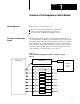
Chapter 2 Installing the Module Interpreting the Indicator Lights The front panel of the analog module contains two bi-color indicators: a red/green RUN/FLT (fault) indicator and a red/green CAL/COM indicator (Figure 2.7). Figure 2.7 Diagnostic Indicators RUN/FLT CAL/COM Run/Fault indicator. This indicator will flash green until the first valid block transfer write has been received. If a fault is found initially or occurs later, the RUN/FLT indicator turns red. Calibrate/communication indicator.
Chapter 3 Communicating With Your Module Chapter Objectives In this chapter, we describe I/O image communication sequence single-transfer programming block-transfer programming module update period I/O Image The temperature control module uses a word of input image table and a word of output image table. Output Image Table High Byte To read the 8 heat TPO bits or 8 cool TPO bits single transferred from the module, read the bits of the high (1) input byte.
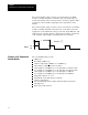
Chapter 3 Communicating with Your Module The low byte of the input image word is used both for single-transfer and block-transfer. For single-transfer, you read this byte to determine whether the high byte of the input image word contains heat bits or cool TPO bits. The high byte of the input image word is used exclusively for single-transfer. This byte contains the control-variable output of each loop as the duty cycle of a bit that is cycled at a regular period (TPO).
Chapter 3 Communicating with Your Module Single Transfer Programming 2. Read (block-transfer) the system status block from the module on a regular basis (using a timer to trigger block-transfers) to monitor the status of the PID loops. The module’s period for updating this temperature data is approximately one second. The module’s period for updating the TPO bits it makes available thru block-transfer is approximately 500ms. 3.
Chapter 3 Communicating with Your Module TPO Bits The loop designations of the heat/cool (control-variable) TPO bits in the high byte of the input image word are as follows.
Chapter 3 Communicating with Your Module The following figure shows an example of PLC-5 ladder logic to handle data single-transferred to/from the 1771-TCM module in an application where the control variable TPO of each loop is used for only heating. This rung examines the low byte of TCM module's input image word to see if it is equal to 3510. If true, it copies the high byte of the TCM module's input image word to the output image byte of the module driving the heating elements.
Chapter 3 Communicating with Your Module Controlling Heating and Cooling Elements In applications where the control variable TPO of each loop is used for both heating and cooling, the ladder logic for data single-transferred to/from the 1771-TCM module must do the following: Step 1 Write the decimal value 35 (binary 00100011) to the high byte of the output image word of the 1771 TCM module. Step 2 Read the low byte of the input image word of the 1771 TCM module.
Chapter 3 Communicating with Your Module This rung examines status bit S:1/15, which is on only during the first program scan, and input image I:004/7, which reflects the state of a bushbutton switch connected to that input. If either is on, it writes the value 3510 to the high byte of the TCM module's input image word. This rung examines the low byte of TCM module's input image word to see if it is equal to 3510.
Chapter 3 Communicating with Your Module In this example: the 1771-TCM module the output modules driving the heating and cooling elements, and the input module providing the input for the manual-start pushbutton switch are in the same I/O chassis with the PLC-5 processor the chassis is set for 1-slot addressing the 1771-TCM module is in slot 1 (I/O group 1) the module driving the heating elements is in slot 2 (I/O group 2) the module driving the cooling elements is in slot 3 (I/O group 3) the module provid
Chapter 3 Communicating with Your Module Block Transfer Write You can generate all block-transfer writes to your 1771-TCM module thru a single block-transfer write instruction. Enter the block length as 64 words. Write your ladder logic so that when you want to send a particular block of data to the 1771-TCM module, you first send it to the 64-word block addressed by the BTW instruction and then use the BTW instruction to send it to the module.
Chapter 3 Communicating with Your Module Block Transfer Read You can generate all block-transfer reads from your 1771-TCM module thru a single block-transfer read instruction. Enter the block length as 64 words.
Chapter 3 Communicating with Your Module Module Update Period The temperature control module generally updates data for single-transfer on a shorter time period than it updates data for block-transfer. The module’s period for updating the heat and cool TPO bits it makes available thru single-transfer is approximately 20ms. The module’s period for updating the heat and cool TPO bits it makes available thru block-transfer is approximately 500ms.
Chapter 4 Configuring the Module Chapter Objectives This chapter shows you how to independently configure each PID loop of the 1771-TCM module.
Chapter 4 Configuring the Module Alarm Dead Band Once the temperature alarm bits are on, they are kept on until the temperature drops below the high alarm by the alarm dead-band value or rise above the low alarm by this value. This dead band provides a hysteresis effect. The dead-band value applies to all alarm values. Low Alarm With Dead Band — When the temperature falls below the user-defined low alarm value, the low alarm bit is turned on .
Chapter 4 Configuring the Module Configuration Block The configuration block contains 23 words as follows: Word Bits Description 1 0-15 Block Identification Code bit 15 . . . . . . . . . . .
Chapter 4 Configuring the Module Word Bits Description 3 0 Always = 0. 1 Control Action • 0 = Control action is • 1 = Control action is E = SP-PV E = PV-SP 2-3 Always = 00. 4 CV Ramping Selects whether to use a fixed CV ramp rate (set in word 4) for PV to reach the set point. • 0 = Disable CV ramping. • 1 = Enable CV ramping. 5-6 Cooling Method bit 6 bit 5 selection • 0 0 = No cooling. • 0 1 = Air cooling. • 1 0 = Oil cooling. • 1 1 = Water cooling. 7 Alarm Enable • 0 = Suppress all alarms.
Chapter 4 Configuring the Module Word Bits Description 13 0-15 Cool Minimum Cycle Time The minimum cycle time in seconds for which the cool bit is on. (0.00 thru 100.00) 14 0-15 Cool Maximum Cycle Time The maximum cycle time in seconds for which the cool bit is on. (0.00 thru 100.00) 15 0-15 Always = 0. 16 0-15 Always = 0. 17 0-15 Low Temperature Alarm Value (0 thru 999.
Chapter 5 Setting Gains Chapter Objectives This chapter shows you how to independently set the gains for each PID loop of the 1771-TCM module. This includes: sequence of block-transfers auto-tuning the loops fine tuning the loops block identification inferred decimal point the configuration block Sequence of Block Transfers At initial start-up, you must write (block-transfer) the gains block to the 1771-TCM module.
Chapter 5 Setting Gains Fine tuning the Loops Set Point Set Point After auto-tuning, you may want to fine-tune the loops. As you fine-tune a loop, first try adjusting the proportional gain; this will have the greatest impact. Your second choice for adjustment should be the integral gain. The derivative gain should be the last choice for fine-tuning a loop.
Chapter 5 Setting Gains Gains Block The gains block contains 57 words as follows: Word Bits Description 1 0-15 Block Identification Code 2 0-15 Loop 1 Heat Proportional Gain 3 0-15 Loop 1 Heat Integral Gain 4 0-15 Loop 1 Heat Derivative Gain 5 0-15 Loop 1 Cool Proportional Gain 6 0-15 Loop 1 Cool Integral Gain 7 0-15 Loop 1 Cool Derivative Gain 8 0-15 Loop 1 Integral Gain Multiplier (0 or 1 = x1 9 0-15 Loop 2 Heat Proportional Gain (0.00 thru 327.
Chapter 5 Setting Gains Word Bits Description 23 0-15 Loop 4 Heat Proportional Gain 24 0-15 Loop 4 Heat Integral Gain 25 0-15 Loop 4 Heat Derivative Gain 26 0-15 Loop 4 Cool Proportional Gain 27 0-15 Loop 4 Cool Integral Gain 28 0-15 Loop 4 Cool Derivative Gain 29 0-15 Loop 4 Integral Gain Multiplier (0 or 1 = x1 30 0-15 Loop 5 Heat Proportional Gain (0.00 thru 327.
Chapter 5 Setting Gains Word Bits Description 51 0-15 Loop 8 Heat Proportional Gain 52 0-15 Loop 8 Heat Integral Gain 53 0-15 Loop 8 Heat Derivative Gain 54 0-15 Loop 8 Cool Proportional Gain 55 0-15 Loop 8 Cool Integral Gain 56 0-15 Loop 8 Cool Derivative Gain 57 0-15 Loop 8 Integral Gain Multiplier (0.00 thru 327.67) (0.000 thru 3.2767) (0.0 thru 3276.7) (0.00 thru 327.67) (0.000 thru 3.2767) (0.0 thru 3276.
Chapter 6 Operating the Module Chapter Objectives This chapter shows you how to control the dynamic block that you send to the 1771-TCM module to control operation of the loops. This includes. sequence of block-transfers block identification inferred decimal point the dynamic block Sequence of Block transfers At initial start-up, you must write (block-transfer) the dynamic block to the 1771-TCM module to establish its mode of operation.
Chapter 6 Operating the Module Dynamic Block The dynamic block contains 34 words as follows: Words 1 thru 34 of the dynamic block are identified by the mnemonics TDC01 thru TDC34 in ProSet 700 software. Word Bits Description 1 0-15 Block Identification Code 2 0 Loop 1 Enable • 0 = Loop 1 disabled. • 1 = Loop 1 enabled if PID control mode selected (bits 7-8, word 2, config block).
Chapter 6 Operating the Module Word Bits Description 6 0 Loop 2 Enable • 0 = Loop 2 disabled. • 1 = Loop 2 enabled if PID control mode selected (bits 7-8, word 2, config block). 1 Loop 2 Auto/Manual Mode Select • 0 = Loop 2 is in the manual mode the manual output value (from word 9) is used as the CV value. • 1 = Loop 2 is in the automatic mode the PID algorithm generates the CV value. 2 Loop 2 Set Point Select • 0 = Select the standby temperature set point value from word 7.
Chapter 6 Operating the Module Word Bits Description 12 0-15 Loop 3 Run Temperature Set point Value 13 0-15 Loop 3 Manual Output Value (CV) 14 0 Loop 4 Enable • 0 = Loop 4 disabled. • 1 = Loop 4 enabled if PID control mode selected (bits 7-8, word 2, config block). 1 Loop 4 Auto/Manual Mode Select • 0 = Loop 4 is in the manual mode the manual output value (from word 17) is used as the CV value. • 1 = Loop 4 is in the automatic mode the PID algorithm generates the CV value.
Chapter 6 Operating the Module Word Bits Description 18 0 Loop 5 Enable • 0 = Loop 5 disabled. • 1 = Loop 5 enabled if PID control mode selected (bits 7-8, word 2, config block). 1 Loop 5 Auto/Manual Mode Select • 0 = Loop 5 is in the manual mode the manual output value (from word 21) is used as the CV value. • 1 = Loop 5 is in the automatic mode the PID algorithm generates the CV value. 2 Loop 5 Set Point Select • 0 = Select the standby temperature set point value from word 19.
Chapter 6 Operating the Module Word Bits Description 24 0-15 Loop 6 Run Temperature Set point Value 25 0-15 Loop 6 Manual Output Value (CV) 26 0 Loop 7 Enable • 0 = Loop 7 disabled. • 1 = Loop 7 enabled if PID control mode selected (bits 7-8, word 2, config block). 1 Loop 7 Auto/Manual Mode Select • 0 = Loop 7 is in the manual mode the manual output value (from word 29) is used as the CV value. • 1 = Loop 7 is in the automatic mode the PID algorithm generates the CV value.
Chapter 6 Operating the Module Word Bits Description 30 0 Loop 8 Enable • 0 = Loop 8 disabled. • 1 = Loop 8 enabled if PID control mode selected (bits 7-8, word 2, config block). 1 Loop 8 Auto/Manual Mode Select • 0 = Loop 8 is in the manual mode the manual output value (from word 33) is used as the CV value. • 1 = Loop 8 is in the automatic mode the PID algorithm generates the CV value. 2 Loop 8 Set Point Select • 0 = Select the standby temperature set point value from word 31.
Chapter 7 Monitoring Status Data Chapter Objectives This chapter shows you how to monitor status data from the 1771-TCM module. This includes. sequence of block-transfers block identification inferred decimal point the system status block Sequence of Block transfers At initial start-up, you must write (block-transfer) the dynamic block to the 1771-TCM module to establish its mode of operation. After that, you must send a dynamic block to the module any time you want to change its operating mode.
Chapter 7 Monitoring Status Data System Status Block The system status block contains 64 words as follows: Word Bits Description 1 0-15 Block Identification Code 2 0 Loop 1 Enable • 0 = Loop 1 disabled. • 1 = Loop 1 enabled. 1 Loop 1 Auto/Manual Mode Select (controlled by bit 1 of word 2 of the dynamic block) • 0 = Loop 1 is in the manual mode the manual output value (from word 5, dynamic block) is used as the CV value.
Chapter 7 Monitoring Status Data Word Bits Description 2 13 Loop 1 CV Ramp Rate (selected in bit 4 of word 3 of the configuration block) • 0 = Loop 1 CV is not ramping. • 1 = Loop 1 CV is ramping at the rate entered in word 4 of the configuration block. 14 Loop 1 Input High TC Range Alarm (based on thermocouple type set in bits 12-15 of word 2 of the configuration block) • 0 = Loop 1 PV input is below the high TC range alarm value. • 1 = Loop 1 PV input is at or above the high TC range alarm value.
Chapter 7 Monitoring Status Data Word Bits Description 5 0 Loop 2 Enable • 0 = Loop 2 disabled. • 1 = Loop 2 enabled. 1 Loop 2 Auto/Manual Mode Select (controlled by bit 1 of word 6 of the dynamic block) • 0 = Loop 2 is in the manual mode the manual output value (from word 9, dynamic block) is used as the CV value. • 1 = Loop 2 is in the automatic mode the PID algorithm generates the CV value. 2 Loop 2 Open Circuit • 0 = Loop 2 thermocouple circuit is closed (connection OK). • 1 = .
Chapter 7 Monitoring Status Data Word Bits Description 5 13 Loop 2 CV Ramp Rate (selected in bit 4 of word 3 of the configuration block) • 0 = Loop 2 CV is not ramping. • 1 = Loop 2 CV is ramping at the rate entered in word 4 of the configuration block. 14 Loop 2 Input High TC Range Alarm (based on thermocouple type set in bits 12-15 of word 2 of the configuration block) • 0 = Loop 2 PV input is below the high TC range alarm value. • 1 = Loop 2 PV input is at or above the high TC range alarm value.
Chapter 7 Monitoring Status Data Word Bits Description 8 0 Loop 3 Enable • 0 = Loop 3 disabled. • 1 = Loop 3 enabled. 1 Loop 3 Auto/Manual Mode Select (controlled by bit 1 of word 10 of the dynamic block) • 0 = Loop 3 is in the manual mode the manual output value (from word 13, dynamic block) is used as the CV value. • 1 = Loop 3 is in the automatic mode the PID algorithm generates the CV value. 2 Loop 3 Open Circuit • 0 = Loop 3 thermocouple circuit is closed (connection OK). • 1 = .
Chapter 7 Monitoring Status Data Word Bits Description 8 13 Loop 3 CV Ramp Rate (selected in bit 4 of word 3 of the configuration block) • 0 = Loop 3 CV is not ramping. • 1 = Loop 3 CV is ramping at the rate entered in word 4 of the configuration block. 14 Loop 3 Input High TC Range Alarm (based on thermocouple type set in bits 12-15 of word 2 of the configuration block) • 0 = Loop 3 PV input is below the high TC range alarm value. • 1 = Loop 3 PV input is at or above the high TC range alarm value.
Chapter 7 Monitoring Status Data Word Bits Description 11 0 Loop 4 Enable • 0 = Loop 4 disabled. • 1 = Loop 4 enabled. 1 Loop 4 Auto/Manual Mode Select (controlled by bit 1 of word 14 of the dynamic block) • 0 = Loop 4 is in the manual mode the manual output value (from word 17, dynamic block) is used as the CV value. • 1 = Loop 4 is in the automatic mode the PID algorithm generates the CV value. 2 Loop 4 Open Circuit • 0 = Loop 4 thermocouple circuit is closed (connection OK). • 1 = .
Chapter 7 Monitoring Status Data Word Bits Description 11 13 Loop 4 CV Ramp Rate (selected in bit 4 of word 3 of the configuration block) • 0 = Loop 4 CV is not ramping. • 1 = Loop 4 CV is ramping at the rate entered in word 4 of the configuration block. 14 Loop 4 Input High TC Range Alarm (based on thermocouple type set in bits 12-15 of word 2 of the configuration block) • 0 = Loop 4 PV input is below the high TC range alarm value. • 1 = Loop 4 PV input is at or above the high TC range alarm value.
Chapter 7 Monitoring Status Data Word Bits Description 14 0 Loop 5 Enable • 0 = Loop 5 disabled. • 1 = Loop 5 enabled. 1 Loop 5 Auto/Manual Mode Select (controlled by bit 1 of word 18 of the dynamic block) • 0 = Loop 5 is in the manual mode the manual output value (from word 21, dynamic block) is used as the CV value. • 1 = Loop 5 is in the automatic mode the PID algorithm generates the CV value. 2 Loop 5 Open Circuit • 0 = Loop 5 thermocouple circuit is closed (connection OK). • 1 = .
Chapter 7 Monitoring Status Data Word Bits Description 14 13 Loop 5 CV Ramp Rate (selected in bit 4 of word 3 of the configuration block) • 0 = Loop 5 CV is not ramping. • 1 = Loop 5 CV is ramping at the rate entered in word 4 of the configuration block. 14 Loop 5 Input High TC Range Alarm (based on thermocouple type set in bits 12-15 of word 2 of the configuration block) • 0 = Loop 5 PV input is below the high TC range alarm value. • 1 = Loop 5 PV input is at or above the high TC range alarm value.
Chapter 7 Monitoring Status Data Word Bits Description 17 0 Loop 6 Enable • 0 = Loop 6 disabled. • 1 = Loop 6 enabled. 1 Loop 6 Auto/Manual Mode Select (controlled by bit 1 of word 22 of the dynamic block) • 0 = Loop 6 is in the manual mode the manual output value (from word 25, dynamic block) is used as the CV value. • 1 = Loop 6 is in the automatic mode the PID algorithm generates the CV value. 2 Loop 6 Open Circuit • 0 = Loop 6 thermocouple circuit is closed (connection OK). • 1 = .
Chapter 7 Monitoring Status Data Word Bits Description 17 13 Loop 6 CV Ramp Rate (selected in bit 4 of word 3 of the configuration block) • 0 = Loop 6 CV is not ramping. • 1 = Loop 6 CV is ramping at the rate entered in word 4 of the configuration block. 14 Loop 6 Input High TC Range Alarm (based on thermocouple type set in bits 12-15 of word 2 of the configuration block) • 0 = Loop 6 PV input is below the high TC range alarm value. • 1 = Loop 6 PV input is at or above the high TC range alarm value.
Chapter 7 Monitoring Status Data Word Bits Description 20 0 Loop 7 Enable • 0 = Loop 7 disabled. • 1 = Loop 7 enabled. 1 Loop 7 Auto/Manual Mode Select (controlled by bit 1 of word 26 of the dynamic block) • 0 = Loop 7 is in the manual mode the manual output value (from word 29, dynamic block) is used as the CV value. • 1 = Loop 7 is in the automatic mode the PID algorithm generates the CV value. 2 Loop 7 Open Circuit • 0 = Loop 7 thermocouple circuit is closed (connection OK). • 1 = .
Chapter 7 Monitoring Status Data Word Bits Description 20 13 Loop 7 CV Ramp Rate (selected in bit 4 of word 3 of the configuration block) • 0 = Loop 7 CV is not ramping. • 1 = Loop 7 CV is ramping at the rate entered in word 4 of the configuration block. 14 Loop 7 Input High TC Range Alarm (based on thermocouple type set in bits 12-15 of word 2 of the configuration block) • 0 = Loop 7 PV input is below the high TC range alarm value. • 1 = Loop 7 PV input is at or above the high TC range alarm value.
Chapter 7 Monitoring Status Data Word Bits Description 23 0 Loop 8 Enable • 0 = Loop 8 disabled. • 1 = Loop 8 enabled. 1 Loop 8 Auto/Manual Mode Select (controlled by bit 1 of word 30 of the dynamic block) • 0 = Loop 8 is in the manual mode the manual output value (from word 33, dynamic block) is used as the CV value. • 1 = Loop 8 is in the automatic mode the PID algorithm generates the CV value. 2 Loop 8 Open Circuit • 0 = Loop 8 thermocouple circuit is closed (connection OK). • 1 = .
Chapter 7 Monitoring Status Data Word Bits Description 23 13 Loop 8 CV Ramp Rate (selected in bit 4 of word 3 of the configuration block) • 0 = Loop-8 CV is not ramping. • 1 = Loop 8 CV is ramping at the rate entered in word 4 of the configuration block. 14 Loop 8 Input High TC Range Alarm (based on thermocouple type set in bits 12-15 of word 2 of the configuration block) • 0 = Loop 8 PV input is below the high TC range alarm value. • 1 = Loop 8 PV input is at or above the high TC range alarm value.
Chapter 7 Monitoring Status Data Word Bits Description 27 0-15 Loop 1 Temperature (range is dependant upon thermocouple type and C/F selection) 28 0-15 Loop 2 Temperature (range is dependant upon thermocouple type and C/F selection) 29 0-15 Loop 3 Temperature (range is dependant upon thermocouple type and C/F selection) 30 0-15 Loop 4 Temperature (range is dependant upon thermocouple type and C/F selection) 31 0-15 Loop 5 Temperature (range is dependant upon thermocouple type and C/F
Chapter 7 Monitoring Status Data Word Bits Description 57 0-15 Loop 7 PID Error Value (-3276.7 thru +3276.7 ) 58 0-15 Loop 8 PID Error Value (-3276.7 thru +3276.7 ) 59 0-15 Cold Junction Compensation Temperature 60 0 Cold Junction Compensation Temperature Low Alarm (0 C thru +70 C) • 0 = Cold junction compensation temperature is 0 C or above. • 1 = Cold junction compensation temperature is below 0 C.
Chapter 7 Monitoring Status Data Word Bits Description 61 8 Loop 1 Input High Temperature Alarm (set in word 18 of the configuration block) • 0 = Loop 1 PV input is below the high temperature alarm value. • 1 = Loop 1 PV input is at or above the high temperature alarm value. 9 Loop 2 Input High Temperature Alarm (set in word 18 of the configuration block) • 0 = Loop 2 PV input is below the high temperature alarm value. • 1 = Loop 2 PV input is at or above the high temperature alarm value.
Chapter 7 Monitoring Status Data Word Bits Description 62 0 Loop 1 Low Deviation Alarm (set in word 19 of the configuration block) • 0 = Loop 1 PV input is above the low deviation alarm value. • 1 = Loop 1 PV input is at or below the low deviation alarm value. 1 Loop 2 Low Deviation Alarm (set in word 19 of the configuration block) • 0 = Loop 2 PV input is above the low deviation alarm value. • 1 = Loop 2 PV input is at or below the low deviation alarm value.
Chapter 7 Monitoring Status Data Word Bits Description 62 6 Loop 7 Low Deviation Alarm (set in word 19 of the configuration block) • 0 = Loop 7 PV input is above the low deviation alarm value. • 1 = Loop 7 PV input is at or below the low deviation alarm value. 7 Loop 8 Low Deviation Alarm (set in word 19 of the configuration block) • 0 = Loop 8 PV input is above the low deviation alarm value. • 1 = Loop 8 PV input is at or below the low deviation alarm value.
Chapter 7 Monitoring Status Data Word Bits Description 63 0 Loop 1 Auto Tuning successful • 0 = Auto tuning was not successful for loop 1 • 1 = Auto tuning was successful in determining PID gains for loop 1. 1 Loop 2 Auto Tuning successful • 0 = Auto tuning was not successful for loop 2 • 1 = Auto tuning was successful in determining PID gains for loop 2.
Chapter 8 Calibrating the Module Chapter Objective In this chapter, for calibrating your module, we describe: tools and equipment when to calibrate calibration methods indicator operation during calibration preparing to calibrate write calibration block read calibration block calibration procedure Tools and Equipment In order to calibrate your temperature control module you will need the following tools and equipment: Tool or Equipment Description Precision Voltage Source 0-10V, 1µV resolution Pre
Chapter 8 Calibrating the Module Calibration Write Block The calibration write block contains 20 words as shown in Table 6.A. Table 6.
Chapter 8 Calibrating the Module Calibration Read Block The calibration read block contains 14 words as shown in Table 6.B. Table 6.B Calibration Read Block Word Bits Description 1 0-15 Block Identification Code 2 0 Bad Calibration Procedure • 0 = OK • 1 = Wrong calibration procedure was attempted with the calibration write block. 1 Calibration Hardware Failure • 0 = OK • 1 = Calibration cannot take place due to hardware failure.
Chapter 8 Calibrating the Module Word Bits Description 5 0 Loop 1 Input Calibration Bad 1 Loop 2 Input Calibration Bad 2 Loop 3 Input Calibration Bad 3 Loop 4 Input Calibration Bad 4 Loop 5 Input Calibration Bad 5 Loop 6 Input Calibration Bad 6 Loop 7 Input Calibration Bad 7 Loop 8 Input Calibration Bad 8-15 Reserved 6 0-15 Reserved 7 0-15 Reserved 8 0-15 Reserved 9 0-15 Reserved 10 0-15 Reserved 11 0-15 Reserved 12 0-15 Reserved 13 0-15 Reserved 14 0-15 Rese
Chapter 8 Calibrating the Module Calibration Procedure You can calibrate any number of loop input channels, in any order. Set up a calibration write block as shown in Table 6.A. Important: In order to allow the module to stabilize, energize the module for at least 30 minutes before calibrating. 1. In the input calibration mask (word 2) of the calibration write block, turn each bit corresponding to each loop you want to calibrate. Refer to Table 6.A. 2.
Chapter 8 Calibrating the Module 10. In the calibration write block a. turn on the calibration high/low bit (word 2, bit 0) b. turn off the calibration clock bit (word 2, bit 1) 11. Send (block-transfer write) the calibration write block to the module. 12. Request (block-transfer read) the calibration read block from the module. If the input-calibration-bad bit in word 5 is off, and the corresponding input-calibration-done bit in word 3 is on, the procedure is complete for the corresponding loop.
Chapter 9 Troubleshooting Chapter Objective We describe how to troubleshoot your module by observing LED indicators. Diagnostics Reported by the Module At power-up, the module turns the RUN/FLT indicator to red, then checks for: correct RAM operation EPROM operation EEPROM operation After passing initial diagnostics, the module turns the RUN/FLT indicator to flashing green. The indicator will continue to flash green until it receives a valid block-transfer write.
Chapter 9 Troubleshooting Troubleshooting with the Indicators Table 7.A shows indications, probable causes and recommended actions to correct common faults which may occur. Table 7.A Troubleshooting Chart Indication Probable Cause Recommended Action No power to module Check power to I/O chassis. Recycle as necessary. Possible short on the module LED driver failure Replace module. Microprocessor, oscillator or EPROM failure Replace module.
Appendix A Specifications General Specifications Number of PID Loops 8 individually isolated I/O Chassis Location any single I/O module slot A/D Resolution 16 bits or 15 bits plus sign bit Input Filtering 6 pole low pass hardware filter Calibration Interval • 6 months for first interval • 1 year for subsequent intervals Isolation Voltage Designed to withstand 1000V dc continuous between input channels and between input and backplane connections.
Appendix A Specifications Temperature Specifications Input p Range g ( l (selectable) bl ) ±105mV Type B: Type E: Type J: Type K: Type R: Type S: Type T: 300 to 1800oC -270 to 1000oC -210 to 1200oC -270 to 1372oC -50 to 1768oC -50 to 1768oC -270 to 400oC Maximum Input Resolution1 3.3µV/bit @ 15 bits with sign bit Type E, J, K, T 0.1°C (0.2°F)2 Type B, R, S: 0.3oC (0.6oF)2 Default Display Resolution 0.1°C (0.
Appendix A Specifications Temperature Resolution of Thermocouple Inputs 0.60 0.55 0.50 Resolution (° C/bit) 0.45 0.40 0.35 0.30 0.25 0.20 0.15 0.10 0.05 0.00 -200 0 200 400 600 800 1000 1200 1400 1600 1800 1832 2192 2552 2912 3272 Temperature (°C) 0.8 0.7 Resolution ( F/bit) 0.6 ° 0.5 0.4 0.3 0.2 0.1 0.
Appendix B Locating Errors In the status file, 2 words per loop provide error codes for their corresponding loop. The first word for each loop indicates configuration-block and gains-block errors for that loop.
Appendix B Locationg Errors The second word for each loop indicates dynamic-block and auto-tuning errors for that loop.
Appendix A Specifications General Specifications Number of PID Loops 8 individually isolated I/O Chassis Location any single I/O module slot A/D Resolution 16 bits or 15 bits plus sign bit Input Filtering 6 pole low pass hardware filter Calibration Interval • 6 months for first interval • 1 year for subsequent intervals Isolation Voltage Designed to withstand 1000V dc continuous between input channels and between input and backplane connections.
Appendix A Specifications Temperature Specifications Input p Range g ( l (selectable) bl ) ±105mV Type B: Type E: Type J: Type K: Type R: Type S: Type T: 300 to 1800oC -270 to 1000oC -210 to 1200oC -270 to 1372oC -50 to 1768oC -50 to 1768oC -270 to 400oC Maximum Input Resolution1 3.3µV/bit @ 15 bits with sign bit Type E, J, K, T 0.1°C (0.2°F)2 Type B, R, S: 0.3oC (0.6oF)2 Default Display Resolution 0.1°C (0.
Appendix A Specifications Temperature Resolution of Thermocouple Inputs 0.60 0.55 0.50 Resolution (° C/bit) 0.45 0.40 0.35 0.30 0.25 0.20 0.15 0.10 0.05 0.00 -200 0 200 400 600 800 1000 1200 1400 1600 1800 1832 2192 2552 2912 3272 Temperature (°C) 0.8 0.7 Resolution ( F/bit) 0.6 ° 0.5 0.4 0.3 0.2 0.1 0.
Appendix B Locating Errors In the status file, 2 words per loop provide error codes for their corresponding loop. The first word for each loop indicates configuration-block and gains-block errors for that loop.
Appendix B Locating Errors In the status file, 2 words per loop provide error codes for their corresponding loop. The first word for each loop indicates configuration-block and gains-block errors for that loop.
Appendix B Locationg Errors The second word for each loop indicates dynamic-block and auto-tuning errors for that loop.
Appendix C Example Ladder Logic Program Appendix Objectives This appendix describes a ladder logic program. This program is for a PLC-5 processor. You can use this program to test the module. Also, by using this program as a model, you can save time in developing a program for your application. Abbreviations In this appendix, we use the following abbrviations.
Appendix C Example Ladder Logic Program Program Files This program uses the following program files.
Appendix C Example Ladder Logic Program TPO Bit File File Word Bit Description B20 0 0 Loop 1 Heat TPO Bit Block Transferred 1 Loop 2 Heat TPO Bit Block Transferred 2 Loop 3 Heat TPO Bit Block Transferred 3 Loop 4 Heat TPO Bit Block Transferred 4 Loop 5 Heat TPO Bit Block Transferred 5 Loop 6 Heat TPO Bit Block Transferred 6 Loop 7 Heat TPO Bit Block Transferred 7 Loop 8 Heat TPO Bit Block Transferred 8 Loop 1 Cool TPO Bit Block Transferred 9 Loop 2 Cool TPO Bit Block Tra
Appendix C Example Ladder Logic Program Download Bits File Word Bit Description B20 0 0 L1C download to TCM required 1 L2C download to TCM required 2 L3C download to TCM required 3 L4C download to TCM required 4 L5C download to TCM required 5 L6C download to TCM required 6 L7C download to TCM required 7 L8C download to TCM required 8 GBC download to TCM required 9 DYC download to TCM required 0 L1C download to TCM in progress 1 L8C download to TCM in progress 2 L3C download t
Appendix C Example Ladder Logic Program Word B26:0 is used by the program file 2 to set the needed download-required bits on power-up of the processor or when the processor is switched from program mode to run mode. If a configuration block-transfer is required while the processor is in the run mode, it requires additional ladder logic to be added to latch the appropriate download-required bit. The program will automatically unlatch the download-required bit after the successful block-transfer.
Appendix C Example Ladder Logic Program Ladder Logic Listing The following is the listing of the ladder logic program. This program is for a 1785 PLC-5 processor. You can use this program to test the module. Also, by using this program as a model, you can save time in developing a program for your application. +––––––––––––––––––––––––––––––––––––––––––––––––––––+ | Allen–Bradley Company | | 6200 Series Software | | PLC–5 Programming Terminal Software | | Release 4.
Appendix C Example Ladder Logic Program Program Listing Report PLC–5/40 Wed Jun 1, 1994 Page 1 File TCM Rung 2:0 Rung 2:0 | DOWNLOAD | | TO TCM | | PLC REQUIRED | | RUNNING BIT–MAP | | FIRST SCAN | | S:1 +MOV–––––––––––––––+ | +––––] [––––––––––––––––––––––––––––––––––––––––––––––––++MOVE ++–+ | 15 ||Source B26:0|| | | || 0000001111111111|| | | ||Destination B21:0|| | | || 0000000000000000|| | | |+––––––––––––––––––+| | | | ENABLE | | | | BTR FROM | | | | TCM | | | | B21 | | | +–––––––––––––(L)––––+ | |
Appendix C Example Ladder Logic Program Program Listing Report PLC–5/40 Wed Jun 1, 1994 Page 2 File TCM Rung 4:0 Rung 4:0 | +MEQ–––––––––––––––+ +BTD–––––––––––––––+ | +–+MASKED EQUAL +––––––––––––––––––––––––––––––––––++BIT FIELD DISTRIB ++–+ | |Source I:002| ||Source I:002|| | | | 37| || 37|| | | |Mask 00FF| ||Source bit 8|| | | | | ||Destination B20:1|| | | |Compare 35| || 0000000000000000|| | | | | ||Destination bit 0|| | | +––––––––––––––––––+ ||Length 8|| | | |+––––––––––––––––––+| | | | TCM OUTPU
Appendix C Example Ladder Logic Program Program Listing Report PLC–5/40 Wed Jun 1, 1994 Page 3 File TCM Rung 30:0 Rung 30:0 | ENABLE | | BTR FROM TCM BTR | | TCM TIMER | | B21 +TON–––––––––––––––+ | +––––]/[–––––––––––––––––––––––––––––––––––––––––––––+TIMER ON DELAY +–(EN)–+ | 48 |Timer T27:0| | | |Time base 0.
Appendix C Example Ladder Logic Program Program Listing Report PLC–5/40 Wed Jun 1, 1994 Page 4 File TCM Rung 30:4 Rung 30:4 The following rung will force the program scan through the Service Complete BTR from TCM Subroutine (Program File #032) each time a successful BTR is completed from the module. The logic in Program File #032 will determine the ID of the status block that has been received, and buffer the new data to its proper working location in the PLC–5 data table.
Appendix C Example Ladder Logic Program Program Listing Report PLC–5/40 Wed Jun 1, 1994 Page 5 File TCM Rung 32:0 Rung 32:0 The following rung will reset the BTR Error Counter (C25:0) assigned to TCM each time a successful BTR is completed from the module.
Appendix C Example Ladder Logic Program Program Listing Report PLC–5/40 Wed Jun 1, 1994 Page 6 File TCM Rung 32:4 Rung 32:4 | BLOCK ID | | OF LAST | | STATUS BLK GAINS | | RECEIVED BLOCK WORD | | FROM TCM #1 | | +EQU–––––––––––––––+ +COP–––––––––––––––+ | +–+EQUAL +––––––––––––––––––––––––––––––––––++COPY FILE ++–+ | |Source A N22:0| ||Source #B24:10|| | | | 255| ||Destination #N38:1|| | | |Source B 9| ||Length 64|| | | | | |+––––––––––––––––––+| | | +––––––––––––––––––+ | REQUEST | | | | GAINS | | | |
Appendix C Example Ladder Logic Program Program Listing Report PLC–5/40 Wed Jun 1, 1994 Page 7 File TCM Rung 32:9 Rung 32:9 | | AUTOTUNE | | AUTOTUNE | FINISHED AUTOTUNE | | COMPLETED| LOOP #2 FINISHED | | LOOP #2 | ONE–SHOT LOOP #2 | | N40:5 B21 B21 | +––––] [–––––––[ONS]–––––––––––––––––––––––––––––––––––––––––––––––––––(L)–––––+ | 7 105 97 | Rung 32:10 | | AUTOTUNE | | AUTOTUNE | FINISHED AUTOTUNE | | COMPLETED| LOOP #3 FINISHED | | LOOP #3 | ONE–SHOT LOOP #3 | | N40:8 B21 B21 | +––––] [–––––––[ONS]–
Appendix C Example Ladder Logic Program Program Listing Report PLC–5/40 Wed Jun 1, 1994 Page 8 File TCM Rung 32:16 Rung 32:16 | MAIN | | PROGRAM | | POINTER #1 | | +MOV–––––––––––––––+ | +–––––––––––––––––––––––––––––––––––––––––––––––––––––––––+MOVE +–+ | |Source 1| | | | | | | |Destination N22:1| | | | 0| | | +––––––––––––––––––+ | Rung 32:17 | MAIN | | LOAD ERROR PROGRAM | | CODES POINTER #2 | | 1 +MUL–––––––––––––––+ | +–––[LBL]–––––––––––––––––––––––––––––––––––––––––––––––––+MULTIPLY +–+ | |Source
Appendix C Example Ladder Logic Program Program Listing Report PLC–5/40 Wed Jun 1, 1994 Page 9 File TCM Rung 32:21 Rung 32:21 | +SUB–––––––––––––––+ | +–––––––––––––––––––––––––––––––––––––––––––––––––––––––––+SUBTRACT +–+ | |Source A F28:0| | | | 0.000000| | | |Source B N22:5| | | | 0| | | |Destination F28:1| | | | 0.
Appendix C Example Ladder Logic Program Program Listing Report PLC–5/40 Wed Jun 1, 1994 Page 10 File TCM Rung 32:25 Rung 32:25 | MAIN | | PROGRAM | | POINTER #3 | | +ADD–––––––––––––––+ | +–––––––––––––––––––––––––––––––––––––––––––––––––––––––––+ADD +–+ | |Source A N22:3| | | | 0| | | |Source B 10| | | | | | | |Destination N22:3| | | | 0| | | +––––––––––––––––––+ | Rung 32:26 | ERROR CODE | | FILE N29 | | WORD | | [N22:3] | | +MOV––––––––––––––––––––+ | +––––––––––––––––––––––––––––––––––––––––––––––––
Appendix C Example Ladder Logic Program Program Listing Report PLC–5/40 Wed Jun 1, 1994 Page 11 File TCM Rung 32:29 Rung 32:29 | +DIV––––––––––––––––––––+ | +––––––––––––––––––––––––––––––––––––––––––––––––––––+DIVIDE +–+ | |Source A N40[N22:2]| | | | 0| | | |Source B 100.0000| | | | | | | |Destination F28:0| | | | 0.000000| | | +–––––––––––––––––––––––+ | Rung 32:30 | +MOV–––––––––––––––+ | +–––––––––––––––––––––––––––––––––––––––––––––––––––––––––+MOVE +–+ | |Source F28:0| | | | 0.
Appendix C Example Ladder Logic Program Program Listing Report PLC–5/40 Wed Jun 1, 1994 Page 12 File TCM Rung 32:33 Rung 32:33 | +MUL–––––––––––––––+ | +–––––––––––––––––––––––––––––––––––––––––––––––––––––––––+MULTIPLY +–+ | |Source A F28:1| | | | 0.000000| | | |Source B 100.
Appendix C Example Ladder Logic Program Program Listing Report PLC–5/40 Wed Jun 1, 1994 Page 13 File TCM Rung 32:37 Rung 32:37 | MAIN | | PROGRAM | | POINTER #1 | | +ADD–––––––––––––––+ | +–––––––––––––––––––––––––––––––––––––––––––––––––––––––––+ADD +–+ | |Source A N22:1| | | | 0| | | |Source B 1| | | | | | | |Destination N22:1| | | | 0| | | +––––––––––––––––––+ | Rung 32:38 | MAIN | | PROGRAM LOAD ERROR | | POINTER #1 CODES | | +LEQ–––––––––––––––+ 1 | +–+LESS THAN OR EQUAL+–––––––––––––––––––––––––––
Appendix C Example Ladder Logic Program Program Listing Report PLC–5/40 Wed Jun 1, 1994 Page 14 File TCM Rung 33:0 Rung 33:0 The following eight rungs latch the request gains block bit when the Autotune finished bit for any of the eight loops is set.
Appendix C Example Ladder Logic Program Program Listing Report PLC–5/40 Wed Jun 1, 1994 Page 15 File TCM Rung 33:4 Rung 33:4 | AUTOTUNE AUTOTUNE | | FINISHED FINISHED | | LOOP #5 LOOP #5 | | B21 B21 | +––––] [––––––––––––––––––––––––––––––––––––––––––––––––––––––––––+–––(U)––––+–+ | 100 | 100 | | | | REQUEST | | | | GAINS | | | |BLOCK BIT | | | | N39:34 | | | +–––(L)––––+ | | 0 | Rung 33:5 | AUTOTUNE AUTOTUNE | | FINISHED FINISHED | | LOOP #6 LOOP #6 | | B21 B21 | +––––] [–––––––––––––––––––––––––––––––
Appendix C Example Ladder Logic Program Program Listing Report PLC–5/40 Wed Jun 1, 1994 Page 16 File TCM Rung 35:0 Rung 35:0 | LOOP #2 | | CONFIG | | BLOCK WORD | | #2 | | +COP–––––––––––––––+ | +–––––––––––––––––––––––––––––––––––––––––––––––––––––––––+COPY FILE +–+ | |Source #N30:2| | | |Destination #N31:2| | | |Length 63| | | +––––––––––––––––––+ | Rung 35:1 | LOOP #3 | | CONFIG | | BLOCK WORD | | #2 | | +COP–––––––––––––––+ | +–––––––––––––––––––––––––––––––––––––––––––––––––––––––––+COPY FILE +–+ |
Appendix C Example Ladder Logic Program Program Listing Report PLC–5/40 Wed Jun 1, 1994 Page 17 File TCM Rung 35:5 Rung 35:5 | LOOP #7 | | CONFIG | | BLOCK WORD | | #2 | | +COP–––––––––––––––+ | +–––––––––––––––––––––––––––––––––––––––––––––––––––––––––+COPY FILE +–+ | |Source #N30:2| | | |Destination #N36:2| | | |Length 63| | | +––––––––––––––––––+ | Rung 35:6 | LOOP #8 | | CONFIG | | BLOCK WORD | | #2 | | +COP–––––––––––––––+ | +–––––––––––––––––––––––––––––––––––––––––––––––––––––––––+COPY FILE +–+ |
Appendix C Example Ladder Logic Program Program Listing Report PLC–5/40 Wed Jun 1, 1994 Page 18 File TCM Rung 40:0 Rung 40:0 As long at the last BTW attempted to TCM was successful, the following rung will continuously force the program scan through the Check for Required Downloads to TCM Subroutine (Program File #042). Program File #042 contains all logic required to determine if a command block download is required to TCM.
Appendix C Example Ladder Logic Program Program Listing Report PLC–5/40 Wed Jun 1, 1994 Page 19 File TCM Rung 42:0 Rung 42:0 | +NOT–––––––––––––––+ | +–––––––––––––––––––––––––––––––––––––––––––––––––––––––––+NOT +–+ | |Source B26:0| | | | 0000001111111111| | | |Destination B21:4| | | | 1111110000000000| | | +––––––––––––––––––+ | Rung 42:1 | DOWNLOAD | | TO TCM | | REQUIRED | | BIT–MAP | | | | +MVM–––––––––––––––+ | +–––––––––––––––––––––––––––––––––––––––––––––––––––––––––+MOVE WITH MASK +–+ | |Source
Appendix C Example Ladder Logic Program Program Listing Report PLC–5/40 Wed Jun 1, 1994 Page 20 File TCM Rung 42:5 Rung 42:5 The following rung, in conjunction with the previous rung, insures that a DYC download to TCM will always occur during the interrupt following the last required static command block download.
Appendix C Example Ladder Logic Program Program Listing Report PLC–5/40 Wed Jun 1, 1994 Page 21 File TCM Rung 42:10 Rung 42:10 Any time the TCM BTW function is in its ”quiescent” state, the following five rungs will compare the DYC words from the PLC–5 data table with the same words that were loaded into the TCM BTW data file (B24:74 – B24:137) upon conclusion of the last successful BTW to TCM (reference the logic in Program File #045).
Appendix C Example Ladder Logic Program Program Listing Report PLC–5/40 Wed Jun 1, 1994 Page 22 File TCM Rung 42:15 Rung 42:15 | CHANGE FND | | DURING DYC | | TCM DYC DOWNLOAD | | WORD FILE TO TCM | | SEARCH REQUIRED | | R23:0 B21 | +––––] [–––––––––––––––––––––––––––––––––––––––––––––––––––––––––––––––(L)–––––+ | FD 9 | Rung 42:16 | CHANGE FND | | DURING | | TCM DYC DOWNLOAD | | WORD FILE TO TCM | | SEARCH REQUIRED | | R23:0 B21 | +––––] [–––––––––––––––––––––––––––––––––––––––––––––––––––––––––––––––(
Appendix C Example Ladder Logic Program Program Listing Report PLC–5/40 Wed Jun 1, 1994 Page 23 File TCM Rung 43:0 Rung 43:0 | L1C | | L1C DOWNLOAD | | DOWNLOAD TO TCM | | TO TCM NOT | | REQUIRED REQUIRED | | B21 0 | +––––]/[––––––––––––––––––––––––––––––––––––––––––––––––––––––––––––––(JMP)––––+ | 0 | Rung 43:1 | ( DATA ) | | (TO TCM ) | | BTW DATA | | FILE | | WORD #01 | | +COP––––––––––––––––––––+ | +––––––––––––––––––––––––––––––––––––––––––––––––––––+COPY FILE +–+ | |Source #N30:1| | | |Destination
Appendix C Example Ladder Logic Program Program Listing Report PLC–5/40 Wed Jun 1, 1994 Page 24 File TCM Rung 43:6 Rung 43:6 | L2C | | DOWNLOAD | | TO TCM | | IN PROGRES | | B21 | +––––––––––––––––––––––––––––––––––––––––––––––––––––––––––––––––––––––(L)–––––+ | 17 | Rung 43:7 | +RET–––––––––––––––+ | +–––––––––––––––––––––––––––––––––––––––––––––––––––––––––+RETURN () +–+ | |Return parameter | | | +––––––––––––––––––+ | Rung 43:8 | L2C | L3C | | DOWNLOAD | L3C DOWNLOAD | | TO TCM | DOWNLOAD TO TCM | |
Appendix C Example Ladder Logic Program Program Listing Report PLC–5/40 Wed Jun 1, 1994 Page 25 File TCM Rung 43:13 Rung 43:13 | ( DATA ) | | (TO TCM ) | | BTW DATA | | FILE | | WORD #01 | | +COP––––––––––––––––––––+ | +––––––––––––––––––––––––––––––––––––––––––––––––––––+COPY FILE +–+ | |Source #N33:1| | | |Destination #B24:74| | | |Length 64| | | +–––––––––––––––––––––––+ | Rung 43:14 | L4C | | DOWNLOAD | | TO TCM | | IN PROGRES | | B21 | +––––––––––––––––––––––––––––––––––––––––––––––––––––––––––––––
Appendix C Example Ladder Logic Program Program Listing Report PLC–5/40 Wed Jun 1, 1994 Page 26 File TCM Rung 43:19 Rung 43:19 | +RET–––––––––––––––+ | +–––––––––––––––––––––––––––––––––––––––––––––––––––––––––+RETURN () +–+ | |Return parameter | | | +––––––––––––––––––+ | Rung 43:20 | L5C | L6C | | DOWNLOAD | L6C DOWNLOAD | | TO TCM | DOWNLOAD TO TCM | | NOT | TO TCM NOT | | REQUIRED | REQUIRED REQUIRED | | 4 B21 5 | +–––[LBL]–––––––]/[–––––––––––––––––––––––––––––––––––––––––––––––––––(JMP)––––+ | 5 |
Appendix C Example Ladder Logic Program Program Listing Report PLC–5/40 Wed Jun 1, 1994 Page 27 File TCM Rung 43:25 Rung 43:25 | ( DATA ) | | (TO TCM ) | | BTW DATA | | FILE | | WORD #01 | | +COP––––––––––––––––––––+ | +––––––––––––––––––––––––––––––––––––––––––––––––––––+COPY FILE +–+ | |Source #N36:1| | | |Destination #B24:74| | | |Length 64| | | +–––––––––––––––––––––––+ | Rung 43:26 | L7C | | DOWNLOAD | | TO TCM | | IN PROGRES | | B21 | +––––––––––––––––––––––––––––––––––––––––––––––––––––––––––––––
Appendix C Example Ladder Logic Program Program Listing Report PLC–5/40 Wed Jun 1, 1994 Page 28 File TCM Rung 43:31 Rung 43:31 | +RET–––––––––––––––+ | +–––––––––––––––––––––––––––––––––––––––––––––––––––––––––+RETURN () +–+ | |Return parameter | | | +––––––––––––––––––+ | Rung 43:32 | L8C | GBC | | DOWNLOAD | GBC DOWNLOAD | | TO TCM | DOWNLOAD TO TCM | | NOT | TO TCM NOT | | REQUIRED | REQUIRED REQUIRED | | 7 B21 8 | +–––[LBL]–––––––]/[–––––––––––––––––––––––––––––––––––––––––––––––––––(JMP)––––+ | 8 |
Appendix C Example Ladder Logic Program Program Listing Report PLC–5/40 Wed Jun 1, 1994 Page 29 File TCM Rung 43:37 Rung 43:37 | ( DATA ) | | (TO TCM ) | | BTW DATA | | FILE | | WORD #01 | | +COP––––––––––––––––––––+ | +––––––––––––––––––––––––––––––––––––––––––––––––––––+COPY FILE +–+ | |Source #N39:1| | | |Destination #B24:74| | | |Length 64| | | +–––––––––––––––––––––––+ | Rung 43:38 | DYC | | DOWNLOAD | | TO TCM | | IN PROGRES | | B21 | +––––––––––––––––––––––––––––––––––––––––––––––––––––––––––––––
Appendix C Example Ladder Logic Program Program Listing Report PLC–5/40 Wed Jun 1, 1994 Page 30 File TCM Rung 44:0 Rung 44:0 The following two rungs will ”continuously” write command data to TCM. The contents of the BTW data file are determined by the logic in Program File #043. The XIC,B24/92 and XIC,B24/93 permissives in the second rung are not required for file operation, but are included in the event that the TCM BTW rung is moved to Program File #002.
Appendix C Example Ladder Logic Program Program Listing Report PLC–5/40 Wed Jun 1, 1994 Page 31 File TCM Rung 44:3 Rung 44:3 The following two rungs will increment the BTW Error Counter (C25:1) assigned to TCM each time an unsuccessful BTW is attempted to the module.
Appendix C Example Ladder Logic Program Program Listing Report PLC–5/40 Wed Jun 1, 1994 Page 32 File TCM Rung 45:0 Rung 45:0 The following rung will reset the BTW Error Counter (C25:1) assigned to TCM each time a successful BTW is completed to the module.
Appendix D Saving Auto Tuning Parameter Values Appendix Objectives This appendix shows you how auto-tuning parameter values are saved by reading the auto-tuning status block from and writing the auto-tuning command block to the 1771-TCM module. Sequence of Block Transfers Once auto-tuning is complete, the auto-tuning status block must be read (block-transferred) from the module to store it in PLC processor memory. The module’s memory is volatile.
Appendix D Saving Auto Tuning Parameter Values Auto Tuning Status/Command Block The auto-tuning status block and auto-tuning command block each contains 57 words as follows: Word Bits Description 1 0-15 Block Identification Code 2 0-15 Loop 1 Auto Tuning Parameter Value #1 3 0-15 Loop 1 Auto Tuning Parameter Value #2 4 0-15 Loop 1 Auto Tuning Parameter Value #3 5 0-15 Loop 1 Auto Tuning Parameter Value #4 6 0-15 Loop 1 Auto Tuning Parameter Value #5 7 0-15 Loop 1 Auto Tuning Parame
Appendix D Saving Auto Tuning Parameter Values Word Bits Description 23 0-15 Loop 4 Auto Tuning Parameter Value #1 24 0-15 Loop 4 Auto Tuning Parameter Value #2 25 0-15 Loop 4 Auto Tuning Parameter Value #3 26 0-15 Loop 4 Auto Tuning Parameter Value #4 27 0-15 Loop 4 Auto Tuning Parameter Value #5 28 0-15 Loop 4 Auto Tuning Parameter Value #6 29 0-15 Loop 4 Auto Tuning Parameter Value #7 30 0-15 Loop 5 Auto Tuning Parameter Value #1 31 0-15 Loop 5 Auto Tuning Parameter Value #2
Appendix D Saving Auto Tuning Parameter Values Word Bits Description 51 0-15 Loop 8 Auto Tuning Parameter Value #1 52 0-15 Loop 8 Auto Tuning Parameter Value #2 53 0-15 Loop 8 Auto Tuning Parameter Value #3 54 0-15 Loop 8 Auto Tuning Parameter Value #4 55 0-15 Loop 8 Auto Tuning Parameter Value #5 56 0-15 Loop 8 Auto Tuning Parameter Value #6 57 0-15 Loop 8 Auto Tuning Parameter Value #7 D-4
Index A connecting wiring, 2 7 control bits, 3 3 A/D resolution, A 1 cooling elements, 3 6 alarm dead band, 4 2 hysteresis, 4 2 D audience, i data table use, i auto tuning, 3 2, 5 1 auto tuning status/command block, D 2 dead band, 4 2 diagnostic indicators, 2 10, 8 1, 9 1 diagnostics, indicators, 9 1 B dynamic block, 6 2 backplane current load, 2 2 block ID configuration block, 4 1 dynamic block, 6 1 gains block, 5 2 status block, 7 1 E electrostatic damage, 2 1 enclosure depth, 2 2 error code
I–2 Index dynamic block, 6 1 gains block, 5 2 related publications, installation, of module, 2 4 ii remote termination panel, 2 2, 2 4 connections, 2 6 resolution, A 1 K S keying, 2 3 saving auto tuning parameter values, D 1 sequence of block transfers, 7 1, D 1 L location for the module, 2 2 sequence of communication, 3 2 setting gains, 5 1, 7 1 M manual organization, sequence of block transfers, 5 1, 6 1 iii module configuration, 4 1 module installation, 2 4 module location, 2 2 single tr
Allen Bradley has been helping its customers improve productivity and quality for 90 years. A B designs, manufactures and supports a broad range of control and automation products worldwide. They include logic processors, power and motion control devices, man machine interfaces and sensors. Allen Bradley is a subsidiary of Rockwell International, one of the world's leading technology companies. With major offices worldwide.