
Owner's manual

Programming and Operation
Chapter 3
33
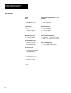
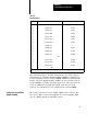
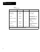
Table 3.A
DAC
Input/Output
Sign Bit Input Bit Pattern Analog Output V
oltage
0 11
1 1
11
1 1
111 10.000V
0 11
1 1
11
1 1
110 9.995V
0 11
1 1
11
1 1
100 9.990V
0
000 0000 001
1 19.5mV
0
000 0000 0010
14.6mV
0
000 0000 0001
9.7mV
0
000 0000 0000
4.9mV
1 11
1 1
11
1 1
111 0
1 11
1 1
11
1 1
110 +4.9mV
1 11
1 1
11
1 1
101 +9.7mV
1 11
1 1
11
1 1
100 +14.6mV
(1)
1
000 0000 001
1 +9.985V
1
000 0000 0001
+9.990V
1
000 0000 0000
(2)
(3)
+9.995V
(1)
LowTRUE Bit Patterns
(2)
= MSBY
(3)
= LSBY
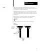
The 12 bit binary input to the DAC is transferred to two bytes using two
write instructions. The Most Significant BYte (MSBY) is eight bits long.
It can be loaded into memory location 600EH. DSEN Line 16 enables the
transfer. The Least Significant BYte (LSBY) can be loaded into memory
location 600DH. It contains data in the upper 4 bits. The lower 4 bits are
not used. DSEN line 15 enables the transfer. DAC data is reset at
power-up or by the data byte reset command (write location 600BH).
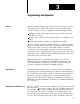
Bit 2 of the control byte is used to inhibit amplifier drive current to the
servo motor. Bit 3 is used to turn OFF the servo motor amplifier. They
are low = TRUE optically isolated TTL outputs.
Control Byte (Servo Motor
Amplifier Inhibit)