Allen Bradley Servo Interface Module (Cat. No.
Table of Contents Introduction . . . . . . . . . . . . . . . . . . . . . . . . . . . . . . . . . . . . 1 1 Description . . . . . . . . . . . . . . . . . . . . . . . . . . . . . . . . . . . . . . . . User Considerations . . . . . . . . . . . . . . . . . . . . . . . . . . . . . . . . . . 1 1 1 2 Component Interfacing, Module Preparation, and Installation . . . . . . . . . . . . . . . . . . . . . . . . . . . . . . 2 1 General . . . . . . . . . . . . . . . . . . . . . . . . . . . . . . . . . . . . . . .
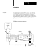
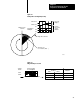
Chapter 1 Introduction Description The Allen-Bradley Servo Interface Module (Cat. No. 1771-SF1) when used with the Micro Controller (Cat. No. 1771-UC1) can control single axis positioning systems such as found in machine tool applications. When combined with a single motor variable speed drive package and a full quadrature encoder, this microprocessor-controlled servo drive system (Figure 1.1) can be programmed to cycle through precise speed and position profiles. Figure 1.
Chapter 1 Introduction User Considerations 1 2 Operating features described in this manual must be totally programmed in the user software (Z-80A opcodes) of the accompanying micro controller. The servo interface module has the capability to perform as described, provided that the software of the micro controller has been completely developed.
Chapter 2 Component Interfacing, Module Preparation, and Installation General This chapter describes the necessary characteristics of user-provided components, preparation and installation of the module and wiring considerations. Refer to the Micro Controller Users Manual (Publication No. 1771-6.5.5) for installation of the micro controller module.
Chapter 2 Component Interfacing, Module Preparation, and Installation TTL Source Current = 7.9mA @ 2.4V +10 to -10V DC analog output for forward or reverse proportional motor speed control. Isolation None of the terminals of the servo interface module are protected against misapplication of AC, DC, or reverse DC. CAUTION: Do not apply voltage or current sources to the terminals of the servo interface module except those specified for the terminals. Damage to the module may result.
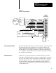
Chapter 2 Component Interfacing, Module Preparation, and Installation Figure 2.
Chapter 2 Component Interfacing, Module Preparation, and Installation The common terminal of the servo interface module should not be used for the shield connection. This terminal is a common with respect to the analog output, TTL outputs and pull-up resistors on the differential inputs. WARNING: Do not use the common terminal of the servo interface module field wiring arm for the shield connection. Unpredictable operation could occur with resulting damage to equipment and/or injury to personnel.
Chapter 2 Component Interfacing, Module Preparation, and Installation Figure 2.2 Example Encoder Diagram (250 Line) Encoder Output Channel A Channel B Counts Decoded on the Module X1 Marker Pulse at 360 o Quadrature Multiplier X2 X4 Single Encoder Line 250 Lines for one rotation (360o ) 10403 Figure 2.
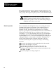
Chapter 2 Component Interfacing, Module Preparation, and Installation Module Installation The module should be located in the I/O slot adjacent to the Micro Controller (Cat. No. 1771-UC1). If located further down the rack, propagation delays due to longer signal paths along the backplane could degrade performance. High-speed communication between the micro controller and servo interface module necessitates this location. The servo interface module must be used with the micro controller.
Chapter 2 Component Interfacing, Module Preparation, and Installation Keying Plastic keying bands shipped with each I/O chassis provide an easy method for keying and I/O slot to accept only one type of module. Use of the keying bands is strongly recommended. The module is slotted in two places on its rear edge. The position of the keying bands on the backplane connector must correspond to the slots to allow insertion of the module so that only the servo interface module will fit in this slot.
Chapter 2 Component Interfacing, Module Preparation, and Installation Specifications Counter Input Analog Output (Single Channel to Servo Amplifier) • Differential • 10V to + 9.995V • Full quadrature encoder • 5mA to +5mA max. Counter Range Max. Cable Distance • 0 25510 • Marker input is latched and reset by user program. • 40 ft. encoder input • 40 ft. TTL output • 5 ft. analog output Max.
Chapter 3 Programming and Operation General The servo interface module controls the operation of a single motor servo drive package in accordance with commands received from the micro controller. Outputs to the servo amplifier of the drive package include: -10.000 to 9.995V analog output signal for proportional motor speed and direction control. A TTL output to limit the drive current from the servo amplifier to the motor. A TTL output signal to turn the servo amplifier ON or OFF.
Chapter 3 Programming and Operation lower 11 bits to the 0 to 10V DC analog output. Bit 12 designates the sign + or - for forward or reverse motion. The resolution of the digital-to-analog conversion is +10V/2048 bits or approximately 4.883 mV/bit. Table 3.A shows the relationship between the input binary number from the micro controller and the analog output voltage from the servo interface module for sample values.
Chapter 3 Programming and Operation Table 3.A DAC Input/Output Sign Bit Input Bit Pattern Analog Output Voltage 0 111 1111 1111 10.000V 0 111 1111 1110 9.995V 0 111 1111 1100 9.990V 0 000 0000 0011 19.5mV 0 000 0000 0010 14.6mV 0 000 0000 0001 9.7mV 0 000 0000 0000 4.9mV 1 111 1111 1111 0 1 111 1111 1110 +4.9mV 1 111 1111 1101 +9.7mV 1 111 1111 1100 +14.6mV (1) 1 000 0000 0011 +9.985V 1 000 0000 0001 +9.990V 000 0000 0000 (3) +9.
Chapter 3 Programming and Operation A write instruction to memory location 600FH latches these bits. DSEN Line 17 enables the transfer from the servo interface module. The control byte is reset at power-up or whenever the data byte reset command is programmed. Encoder Counter Values (Position Pulses) The encoder line drivers generate pulses for each encoder line. Assume that a 250 line encoder is used as in Figure 2.2.
Chapter 3 Programming and Operation Marker A low = TRUE signal is transmitted to status port bit 0 after the marker signal is latched by the servo interface module for each completed revolution of the encoder shaft. A write instruction to 600AH will reset this latched output. A>B A low = TRUE signal appears at status port bit 1 whenever the target value (preset) is greater than the accumulated value of the counters counting the encoder pulses.
Chapter 3 Programming and Operation Table 3.B Servo Control Features Control Function Memory Address DSEN Line Comments DAC Data, MSBY 600EH Write 16 8 bit byte DAC Data, LSBY 600DH Write 15 Upper 4 bits of byte Target Value Preset 600CH Write 14 0 25510 in binary Control Byte 600FH Write 17 Bit 2 limits drive current . Bit 3 turns OFF the servo amplifier.
Allen Bradley, a Rockwell Automation Business, has been helping its customers improve pro ductivity and quality for more than 90 years. We design, manufacture and support a broad range of automation products worldwide. They include logic processors, power and motion control devices, operator interfaces, sensors and a variety of software. Rockwell is one of the worlds leading technology companies. Worldwide representation.