
Owner manual
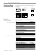
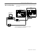
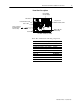
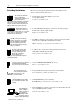
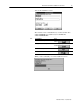
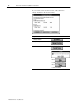
Table Of Contents
- Communication Networks Library
- 1787-5.5, DeviceNet Seminar, Installation Instructions
- When to Use These Instructions
- Meeting the Computer Requirements
- What You Should Receive with the DeviceNet Demo
- Referring to Related Publications
- What's In the Demo Boxes
- Describing the Hardware
- Installing the Software
- Copying Files from the Seminar Disk
- Connecting the Boxes
- Checking the Diagnostics
- Connecting the RS-232 Interface Module
- Checking the RS-232 Module Diagnostics
- Testing the RS-232 Module
- Troubleshooting Your 1747-SDN Scanner Module
- Back Cover
DeviceNet Seminar Installation Instructions
6
Publication
17875.5 - December 1995
These are the descriptions and DeviceNet node numbers of the
devices contained in the demo boxes.
• An I/O chassis with a SLC 500 processor and
a 1747-SDN scanner.
Scanner node number = 00
• A 1794-ADN Flex I/O adapter connected to an analog output
module and a discrete input module.
Adapter node number = 02
• An SMP-3 solid-state overload relay connected to the DeviceNet
network via a 1203-GK5 communication module.
SMP-3 solid-state overload relay node number = 03
• A 1305 ac drive connected to the DeviceNet network via a
1203-GK5 communication module.
1305 ac drive node number = 04
• A Series 9000 PHOTOSWITCH
photoeye.
Photoeye node number = 07
• A DeviceLink discrete I/O connected to a limit switch.
DeviceLink discrete I/O node number = 10
• A RediSTATION operator interface.
RediSTATION operator interface node number = 15
• DeviceNetManager software connected to the DeviceNet network
via a 1770-KFD interface module
.
Software node number = 62
Describing the Hardware
The scanner is the DeviceNet
master coordinating all
communications to all devices on
the DeviceNet network.
This DeviceNet data is transferred to and from the
SLC 500 processor via block and discrete I/O
transfers. This data is then used in the SLC 500
ladder program to do the actual control logic.
Analog output channel 0 is
connected to a volt meter to
easily display the voltage output. Also a 4position
selector switch is connected to bits 0 3 of the
1794IB16 discrete input module.
The SMP3 solidstate overload relay
provides solidstate motor overcurrent
protection in addition to ground fault
protection, jam/stall protection, and
protection against damage caused by
phase loss conditions.
The 1305 ac drive provides drive
status and diagnostic data at the
local panel using the part of the
drive known as the Human
Interface Module or at a
supervisory control station using an optional
communication module.
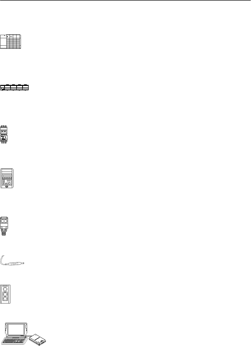
The Series 9000 photoeye is designed
to withstand harsh environments.
The sensor for this lab is retroreflective.
The DeviceLink discrete I/O
connects single nonDeviceNet
dc source devices to the
DeviceNet network.
The RediSTATION operator interface
has a start button, stop button, and a
red light.
DeviceNetManager
software configures
software parameters of
DeviceNet devices
from multiple vendors
and performs network
diagnostic and troubleshooting.