
Owner manual
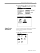
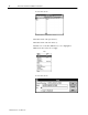
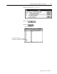
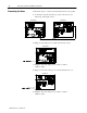
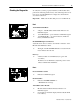
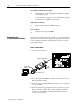
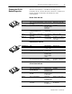
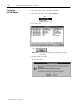
Table Of Contents
- Communication Networks Library
- 1787-5.5, DeviceNet Seminar, Installation Instructions
- When to Use These Instructions
- Meeting the Computer Requirements
- What You Should Receive with the DeviceNet Demo
- Referring to Related Publications
- What's In the Demo Boxes
- Describing the Hardware
- Installing the Software
- Copying Files from the Seminar Disk
- Connecting the Boxes
- Checking the Diagnostics
- Connecting the RS-232 Interface Module
- Checking the RS-232 Module Diagnostics
- Testing the RS-232 Module
- Troubleshooting Your 1747-SDN Scanner Module
- Back Cover
DeviceNet Seminar Installation Instructions
18
Publication
17875.5 - December 1995
1203-GK5 Communication Adapter
✓
Both indicators on the 1203-GK5 Communication Adapter
are illuminated green
If not, check the connections to the communication adapter
and the ac drive or SMP-3 overload relay.
SMP-3 Overload Relay
✓
Power Status indicator is illuminated green
1305 AC Drive
✓
Display reads Stopped +0.00Hz
You must have an RS-232 interface module connected and supplied
with power to run the software. Follow the appropriate directions to
power your RS-232 interface module from the network or a 9V dc
power-supply adapter.
Power From Network
1. Set the power switch to 1.
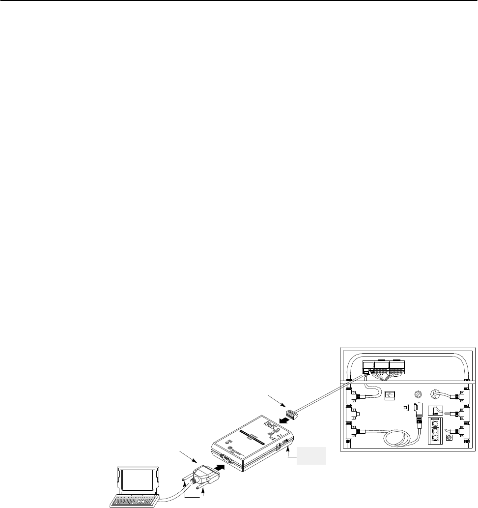
9pin Dshell
RS232 connector
power
switch
retentive locking screws
5pin unsealed connector
2. Insert the 9-pin D-shell RS-232 connector into the bottom of the
RS-232 interface module.
3. Insert the other 9-pin D-shell RS-232 connector into a serial port
of your computer.
4. Insert the network’s 5-pin unsealed connector into the top of the
RS-232 interface module. This connects the RS-232 interface
module onto the trunk line enabling communication between
devices on the network.
Connecting the
RS232 Interface Module