
Owner manual
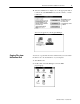
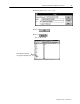
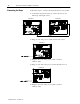
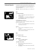
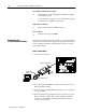
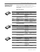
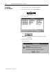
Table Of Contents
- Communication Networks Library
- 1787-5.5, DeviceNet Seminar, Installation Instructions
- When to Use These Instructions
- Meeting the Computer Requirements
- What You Should Receive with the DeviceNet Demo
- Referring to Related Publications
- What's In the Demo Boxes
- Describing the Hardware
- Installing the Software
- Copying Files from the Seminar Disk
- Connecting the Boxes
- Checking the Diagnostics
- Connecting the RS-232 Interface Module
- Checking the RS-232 Module Diagnostics
- Testing the RS-232 Module
- Troubleshooting Your 1747-SDN Scanner Module
- Back Cover
DeviceNet Seminar Installation Instructions
17
Publication
17875.5 - December 1995
To verify that you have properly installed your DeviceNet demo,
perform the following checks. If any of the following items are not
true, refer to the DL10 Dataliner for diagnostics and check the
associated connections.
Important: Make sure the SLC 5/03 processor is in Run mode.
Box 1
1794-ADN Flex I/O Rack
✓
Adapter – both Mod/Net and I/O Status indicators are
illuminated green
✓
1794-OE4 Module – power indicator is illuminated green
✓
1794-IB16 Module – one of the indicators (number 0
thru 3) is illuminated amber
RediSTATION Operator Interface
Adjust the demo selector switch so the number 1 indicator on the
IB16 module illuminates amber.
✓
The light on the RediSTATION flashes red each time the
meter indicates 0 or 10 volts
Photoeye
✓
All three indicators are illuminated (two green and
one amber)
If all three are not illuminated, adjust the position of the
reflector until all three illuminate.
Box 2
DeviceLink Discrete I/O
✓
Indicator is illuminated green
DL10 Dataliner
✓
Indicates SYSTEM NORMAL or
‘‘THANK YOU” message
1747-SDN Scanner Module
✓
Module Status and Network Status indicators are
illuminated green
✓
Node Address and Status display indicates
00 (the SDN
node address)
Checking the Diagnostics