Installation Instructions DeviceNet Seminar Installation Instructions When to Use These Instructions Use these installation instructions to set up the lab for the DeviceNet seminar.
DeviceNet Seminar Installation Instructions What You Should Receive with the DeviceNet Demo You should receive these items as part of the DeviceNet seminar lab exercises. 1 seminar binder 2 power cords 1747 PIC personal computer interface converter 2 demo boxes 1770 KFD Referring to Related Publications DeviceNet Sales Literature Refer to these publications for more information about the DeviceNet network.
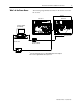
DeviceNet Seminar Installation Instructions What's In the Demo Boxes 3 The following diagram illustrates what’s in the demo boxes for the lab exercises. drop line demo box 1 demo box 2 personal computer (not included) DH 485 link1 RS 232 cable to DH 485 port on processor1 1747 PIC personal computer interface converter RS 232 cable 1770 KFD 1 If you use an SLC 5/04 processor, a Data Highway Plus link is required. Note: Demo is supplied with an SLC 5/04 processor. Publication 1787 5.
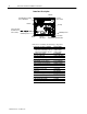
DeviceNet Seminar Installation Instructions Demo Box 1 Description trunk line 4 position selector switch FLEX I/O adapter, terminal bases, and modules voltmeter T Port tap power cord (can be used with 110V or 220V ac outlet) terminating resistor terminating resistor drop line photoeye and reflector power switch RediSTATION operator interface Demo Box 1 includes the following components.
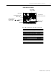
DeviceNet Seminar Installation Instructions Demo Box 2 Description DL10 Dataliner message display limit switch SLC processor with DeviceNet scanner DeviceLink discrete I/O 1305 ac drive power cord (can be used with 110V or 220V ac outlet) SMP 3 solid state overload relay electric motor 1203 GK5 communication module Demo Box 2 includes the following components.
DeviceNet Seminar Installation Instructions Describing the Hardware These are the descriptions and DeviceNet node numbers of the devices contained in the demo boxes. The scanner is the DeviceNet master coordinating all communications to all devices on the DeviceNet network. This DeviceNet data is transferred to and from the SLC 500 processor via block and discrete I/O transfers. This data is then used in the SLC 500 ladder program to do the actual control logic.
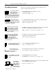
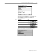
DeviceNet Seminar Installation Instructions Installing the Software Follow these steps to install the software. 1. Start Windows. 2. Insert the software disk into the 3.5” disk drive. 3. From the File menu in the Program Manager, choose Run. File 4. Type a:setup.exe at the Command Line. If you inserted the software disk into another disk drive, use the appropriate drive letter instead of a: 5. Choose You see this installation screen. 6. Choose Continue to proceed with the installation process.
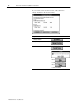
DeviceNet Seminar Installation Instructions 7. Click on the respective fields and enter your name, your company’s name, and the serial number noted on the disk label. We recommend that you enter this information so, in the event that you need to call Allen Bradley for support, the software serial number will be readily available to you. The software serial number is located on the envelope that contained the software disk. 8. Choose You see the registration screen with the information you entered.
DeviceNet Seminar Installation Instructions You see this installation screen. The software creates a default directory on the host hard drive called DNETMGR and a subdirectory for all EDS files called DNETMGR/EDS. 10. If you want to Use the default settings Then Choose Change the default settings a. Make any changes b. Choose Exit the installation process Choose Find out more about this installation Choose When you choose Install, you see this installation screen. Publication 1787 5.
DeviceNet Seminar Installation Instructions If you see this screen, another version of the software is already installed on the host hard drive. If you want to Place the current installation over the existing installation Change the target directories Choose and go to step 10 Cancel the installation You see this screen. Choose to continue with the installation or choose to exit the installation. Publication 1787 5.
DeviceNet Seminar Installation Instructions 11 11. Once the installation is complete, choose the appropriate button to either look at the README notes, run the software, or return to Windows. The README file contains last minute changes to the software or the DeviceNetManager Software User Manual. An icon now appears in your Program Manager. Copying Files from the Seminar Disk You need to copy the files from the seminar disk you received with the demo boxes onto the hard drive of your computer. 1.
DeviceNet Seminar Installation Instructions You see this screen. 3. Choose You see this screen. 4. Double-click on the dnetmgr directory. 5. Click once on the seminar directory so it is highlighted. 6. From the File menu, choose Copy. File Publication 1787 5.
DeviceNet Seminar Installation Instructions 13 You see this screen. 7. In the To field, enter c:\dnetmgr. 8. Choose 9. Choose You see this screen. Notice that the seminar directory now appears in the dnetmgr directory. 10.Choose Publication 1787 5.
DeviceNet Seminar Installation Instructions You see this screen. 11. Double-click on the ipds directory. 12.Double-click on the arch directory. 13.Click once on the SLC 500 directory so it is highlighted. 14.From the File menu, choose Copy. File You see this screen. Publication 1787 5.
DeviceNet Seminar Installation Instructions 15 15.In the To field, enter c:\dnetmgr. 16.Choose 17.Choose You see this screen. Notice that the arch directory now appears in the ipds directory. Publication 1787 5.
DeviceNet Seminar Installation Instructions Connecting the Boxes Follow these steps to connect your DeviceNet demo boxes together. 1. Connect the drop line from the top of box 2 into the second T-Port tap on the right of box 1. Demo Box 1 Demo Box 2 drop line 2. Plug one end of the power cord into the left side of box 1. Demo Box 1 3. Plug the other end of the power cord into a 110V or 220V ac outlet. 4. Plug one end of the other power cord into the back of box 2. Demo Box 2 5.
DeviceNet Seminar Installation Instructions Checking the Diagnostics 17 To verify that you have properly installed your DeviceNet demo, perform the following checks. If any of the following items are not true, refer to the DL10 Dataliner for diagnostics and check the associated connections. Important: Make sure the SLC 5/03 processor is in Run mode.
DeviceNet Seminar Installation Instructions 1203-GK5 Communication Adapter ✓ Both indicators on the 1203-GK5 Communication Adapter are illuminated green If not, check the connections to the communication adapter and the ac drive or SMP-3 overload relay. SMP-3 Overload Relay ✓ Power Status indicator is illuminated green 1305 AC Drive ✓ Connecting the RS 232 Interface Module Display reads Stopped +0.
DeviceNet Seminar Installation Instructions Checking the RS 232 Module Diagnostics 19 The three status indicators on the RS-232 module give you information about your network and its connections. Conditions for this lab should be as indicated in the shaded areas of the following tables. Module Status Indicator If the indicator is Off Solid green Blinking green Solid red Blinking red Then Which indicates There is no power being supplied to There is no power. the module.
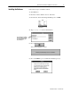
DeviceNet Seminar Installation Instructions Testing the RS 232 Module Follow these steps to test your online connection. 1. From the Who menu, choose Network Who. Who You see this screen. 2. Once nodes 00, 02, 03, 04, 07, 10, 15, and 62 are listed, choose Important: You must complete steps 3 through 8 for each lab station. 3. Double-click on node 04. You see this screen. Publication 1787 5.
DeviceNet Seminar Installation Instructions 21 4. To create an EDS file, choose You see this screen. 5. Choose You see this screen. 6. Choose Once the EDS files are uploaded, the Create EDS File screen is updated with the selected device’s information. We recommend you enter the catalog number. Publication 1787 5.
DeviceNet Seminar Installation Instructions 7. To save the EDS file you’ve just created, choose You see this warning message. 8. To save the EDS file, choose You return to this screen. 9. Complete steps 1 through 8 for node 03, (SMP-3 overload relay). Troubleshooting Your 1747 SDN Scanner Module If the indicator is Off DeviceNet module status indicator STATUS MODULE NET ADDRESS/ERROR The bicolor (green/red) module status indicator (MODULE) displays module status.
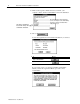
DeviceNet Seminar Installation Instructions 23 The DeviceNet channel has a bicolor (green/red) network status indicator (NET). The following table provides troubleshooting information about the DeviceNet channel communication link. If the NET indicator is Off Then The device has no power or the channel is disabled for communication due to bus off condition, loss of network power, or has been intentionally disabled. Which indicates The channel is disabled for Device Net communication.
DeviceNet Seminar Installation Instructions If the numeric code is Which indicates 79 Module has failed to transmit a message. Check for disconnected cables. Do nothing. Do nothing. Check scan list table entry for slave device to make sure that input and output data lengths are correct. Check slave device configuration. Check accuracy of scan list table entry. Check slave device configuration. 80 81 82 Module is in IDLE mode. Module is in FAULT mode.
DeviceNet Seminar Installation Instructions 25 DeviceNet is a trademark of the Open DeviceNet Vendor Association. PHOTOSWITCH and PLC are registered trademarks of Allen-Bradley Company, Inc. The following are trademarks of Allen-Bradley Company, Inc.: DeviceNetManager, FLEX I/O, SLC, Data Highway Plus, RediSTATION, Dataliner, and DeviceLink. Windows, Windows 95, and Windows NT are trademarks of Microsoft Corporation. Microsoft is a registered trademark of Microsoft Corporation.