
User Manual


Chapter 6
6–1
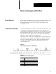
Troubleshooting
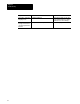
The following table may be used to identify the probable cause of
difficulties with the 1771–QRD Module during initial installation.
Symptom Probable Causes Possible Solutions
No indicators lit Power not applied Check that power supply is turned on
Green light off Power not applied Firmly reseat module in backplane
Red, green indicators solid,
yellow indicator flashing
Rate overrange Decrease input frequencies
Check connection of cable shield(s)
Move signal cable away from
electrical noise sources
Yellow light off Wrong rack, group, slot address used in block
transfer rung
Processor in Program Mode
Wrong address setting on chassis switches
Verify correct address in ladder rung
for block transfer (See table 4.3)
Set to run mode
Verify chassis switch settings
No block transfer writes
done
Wrong rack, group, slot address
Wrong address setting on chassis switches
Verify correct address in ladder rung
for block transfer (See table 4.3)
Verify chassis switch settings
No block transfer reads
done
Wrong rack, group, slot address
Wrong address setting on chassis switches
Verify correct address in ladder rung
for block transfer (See table 4.3)
Verify chassis switch settings
All zeros in data table, red,
green indicators solid,
yellow indicator flashing
Frequency overrange Decrease input frequencies
Check connection of cable shield(s)
Move signal cable away from
electrical noise sources
Data table values not being
incremented; no rate
Wrong signal type or low signal voltage Verify jumpers between terminals 17
and 19, and/or terminals 17 and 20
on the swingarm.
Jumper is ONLY used for TTL
signals.
Verify input voltage levels
Chapter
Objectives