
User Manual


More on Overrange and Overflow
Chapter 5
5–2
Each time an input for one (or more) of the channels is greater than 10.0
kHz, the overrange flag for that channel is set; for example, if the input
frequency for channel 1 is greater than 10.0 kHz, bit #4 is set. (This is the
first bit of the overrange group.)
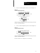
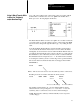
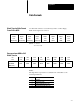
Acknowledge Word = 1010 = 0001 XXXX XXX1 0000
Overrange, Channel 1
If the input frequency for any other channel is greater than 10.0 kHz, the
QRD sets the appropriate bit in the acknowledge code. It is possible for all
channels to be in an overrange condition; in such a case, the acknowledge
code would be:
Acknowledge Word = 10F0 = 0001 XXXX 1111 00000
All inputs are overrange (u10.0 kHz)
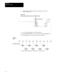
The overflow flags work in the same manner as the overrange flags. As an
example, when totalizer #1 has reached its maximum (32,767), an
overflow flag (bit #8) is set in the acknowledge code. If the acknowledge
code is put in binary format, it looks like this:
Acknowledge Code = 1100 = 0001 XXX1 XXXX 0000
Overflow, Channel 1
Any or all of the four channels can overflow, and any or all of the overflow
flags can be reset using a Block Transfer Write command. If all of the
channels overflow, the acknowledge code will look like:
Acknowledge Code = 1F00 = 0001 1111 XXXX 0000
All inputs are overflowed (u32,767)
Totalizer
Overflow Flags