
User Manual

Module Programming
Chapter 4
4–11
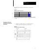
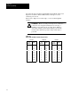
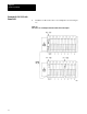
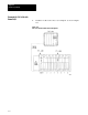
6. Enter the Block Transfer Rung found in Figure 4.12 into the
PLC–5/15.
Figure
4.12
Block T
ransfer Rung for a PLC-5/15 W
ith Remote I/O
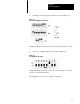
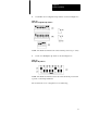
7. Place the PLC–5/15 Processor in RUN mode.
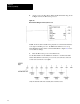
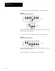
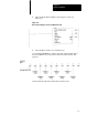
Use the DATA MONITOR to examine data table address N36:0. This is
where the QRD has stored the data from the four channels. They will
appear as:
Only the channels which are actually driven will be active.