
User Manual

Module Programming
Chapter 4
4–5
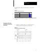
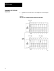
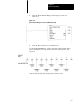
2. Set the PLC–5/15 configuration switches as shown in Figure 4.4.
Figure
4.4
PLC-5/15 Configuration Dip Switches
NOTE: The black area indicates the selected switch position (up or down).
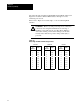
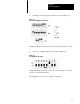
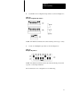
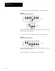
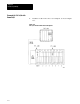
3. Set the 1771 backplane dip switch as shown in Figure 4.5.
Figure
4.5
1771 Backplane Dip Switch.
NOTE: The black area indicates where the switch should be pressed with
a pencil or other sharp instrument.
The backplane is now set up for 2 (dual) slot addressing.