771-QRD Pulse Flowmeter Module Installation and User’s Manual
Important This module is designed for use ONLY as an operating control. Where an operating control failure would result in personal injury and/or loss of property, it is the responsibility of the system designer or end user to add devices (safety, limit controls) or other systems (alarm, supervisory systems) that protect against or warn of control failure. Solid state equipment has operational characteristics differing from those of electromechanical equipment.
Table of Contents Before You Begin . . . . . . . . . . . . . . . . . . . . . . . . . . . . . . . . 1 Manual's Purpose . . . . . . . . . . . . . . . . . . . . . . . . . . . . . . . . . . . Audience . . . . . . . . . . . . . . . . . . . . . . . . . . . . . . . . . . . . . . . . . . Vocabulary . . . . . . . . . . . . . . . . . . . . . . . . . . . . . . . . . . . . . . . . Overview of the Manual . . . . . . . . . . . . . . . . . . . . . . . . . . . . . . . Warnings and Cautions . . . . . . . . . . . . . . .
ii Table of Contents More on Overrange and Overflow . . . . . . . . . . . . . . . . . . . 1 Chapter Objectives . . . . . . . . . . . . . . . . . . . . . . . . . . . . . . . . . . . Frequency Overrange Flags . . . . . . . . . . . . . . . . . . . . . . . . . . . . Totalizer Overflow Flags . . . . . . . . . . . . . . . . . . . . . . . . . . . . . . . Using A Block Transfer Write to Reset the Totalizer(s) and/or Overflow Flags . . . . . . . . . . . . . . . . . . . . . . . . . . . . . . Chapter Summary . . .
Chapter 1 Before You Begin Manual's Purpose This manual shows you how to apply the 1771–QRD Pulse Flowmeter Module to an Allen-Bradley PLC system. It describes methods for installation, programming, and troubleshooting the module. It also provides examples of how to use the module. Audience You must be able to program and operate an Allen-Bradley programmable controller to make efficient use of this module. In particular, you must know how to program Block Transfer instructions.
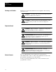
Chapter 1 Before You Begin Warnings and Cautions Warnings are found in this manual and on the equipment. The following symbols are used: WARNING: A warning symbol means people might be injured if the the procedures are not followed. CAUTION: A caution symbol is used when machinery could be damaged if the procedures are not followed. Explosion Hazard Explosion Hazard WARNING: Explosion hazard — substitution of components may impair suitability for Class 1.
Chapter 1 Before You Begin Product Compatibility Do not put the module Do not put the module in the same module group as a discrete high-density module with 2 slot addressing. Avoid placing the module adjacent to AC modules or high voltage DC modules. Related Publications Consult the Allen-Bradley Industrial Computer Group Publications Index (SD 499) for more information about programmable controllers.
Chapter 1 Before You Begin 1–4
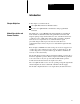
Chapter 2 Introduction Chapter Objectives In this chapter you will read about: 1771–QRD Pulse Flowmeter Module features How the 1771–QRD Module communicates with programmable controllers Module Description and General Features The Catalog No. 1771–QRD Pulse Flowmeter Module is an intelligent block transfer module that interfaces Programmable Controllers with magnetic pickups, single channel shaft encoders, and turbine flowmeters, or with any source of TTL pulses.
Chapter 2 Introduction How the 1771-QRD Works Figure 2.1 A Typical Channel The QRD is operated with block transfers. Block Transfer Reads report the count values, rates, and both overrange and overflow flags to the PLC. Block Transfer Writes are used by the PLC to reset the total count or to reset the overflow flags.
Chapter 2 Introduction How the 1771-QRD Communicates With Programmable Controllers The following is a step-by-step example of the information flow to and from a 1771–QRD Module (Figure 2.2): 1. External devices (magnetic pickups, single channel encoders) generate signals that are conducted to the 1771–QRD module. 2. The 1771–QRD module converts the incoming signals into counts and rates, then stores these values until the PLC requests a transfer of data. 3.
Chapter 3 Installation Chapter Objective In this chapter you will read how to install the 1771–QRD module in the I/O chassis. Installing the 1771-QRD Module Read this installation section completely before installing the module. Double check all connections before you begin programming. WARNING: Disconnect and lock out all power from the controller and system power supplies before installing and wiring modules to avoid injury to personnel and damage to equipment.
Chapter 3 Installation Module Location in the I/O Chassis Place the module in any I/O module slot of the I/O chassis except for the extreme left slot. This slot is reserved for the programmable controllers or adapter modules. In addition: 1. Do not put the module in the same module group as a discrete high-density module with 2-slot addressing. However, other single-slot modules may be placed in the same module group. 2.
Chapter 3 Installation The sensor cable must be shielded. The shield must extend the length of the cable, but be connected only at the 1771–QRD end. The recommended sensor wiring cable type is Belden 8761 or similar. The functions of the individual terminals of the field wiring arm are shown in Figure 3.1. The wiring diagrams for both magnetic pickups and TTL are shown in Figures 3.2 and 3.3, respectively.
Chapter 3 Installation Figure 3.1 Field Wiring Arm WARNING: Explosion hazard. Do not disconnect equipment unless power has been switched off or the area is known to be nonhazardous. AVERTISSEMENT: Risque d’explosion. Avant de déconnecter l’équipment, couper le courant ou s’assurer que l’emplacement est designe non dangereux.
Chapter 3 Installation Figure 3.
Chapter 3 Installation Figure 3.3 Wiring for Active TTL Drivers Note: The jumper between terminals 17 and 19 changes the sensitivity of channels 3 and 4 so that they are compatible with TTL pulses. The jumper between terminals 17 and 20 changes the sensitivity of channels 1 and 2 so that they are compatible with TTL pulses. Signal types may not be mixed within a channel pair. For use with magnetic pickups or turbine flowmeters, do not connect a jumper to these terminals.
Chapter 3 Installation Indicators There are three indicator LEDs on the front panel. The indicator LED functions are listed in Table 3.A. Table 3.A Indicators Chapter Summary Legend Color Type Function FAULT Red Solid One or more inputs are above 10.0 kHZ FAULT Red Flashing Internal hardware failure, or input rates drifiting above and below 10.
Chapter 4 Module Programming Chapter Objectives In this chapter you will learn about: Reading data from the 1771–QRD module Writing data to the 1771–QRD module Black transfer programming format Programming techniques Reading Data From The Module Block Transfer Read programming moves 9 words from the 1771–QRD Module to the processor’s data table. The ladder program initiates the request to transfer data from the QRD to the processor. Figure 4.
Chapter 4 Module Programming Word 0 (1000) is the header code that identifies the data source as a 1771–QRD module. When the module is active, it also contains the status of the overrange and overflow flags. Overrange and overflow are discussed in more detail in the next section of this chapter. Word #1 contains the rate of the signal on channel 1; word #2 contains the total number of pulses received on channel 1.
Chapter 4 Module Programming The following table outlines the examples that are contained in this chapter: Table 4.A Examples Contained in This Section Example Number System Type Page 1 PLC-5/15 in a local 1771 backplane 4-3 2 PLC-5/15 with Remote I/O 4-8 3 PLC-3/10 with Remote I/O 4-12 These examples represent the most common configurations for a controller system. One of them should be close enough to your application to be used as a guide.
Chapter 4 Module Programming The eight physical slots labeled with Rack/Group/Slot (RGS) addresses in Figure 4.2 would have different RGS addresses if single or 1/2 slot addressing were chosen. Please refer to Figure 4.3 for dual, single, or 1/2 slot addressing RGS numbers. WARNING: Remove system power and power to all devices connected to the swing arm terminals before removing or installing your module into the 1771 I/O chassis.
Chapter 4 Module Programming 2. Set the PLC–5/15 configuration switches as shown in Figure 4.4. Figure 4.4 PLC-5/15 Configuration Dip Switches NOTE: The black area indicates the selected switch position (up or down). 3. Set the 1771 backplane dip switch as shown in Figure 4.5. Figure 4.5 1771 Backplane Dip Switch. NOTE: The black area indicates where the switch should be pressed with a pencil or other sharp instrument. The backplane is now set up for 2 (dual) slot addressing.
Chapter 4 Module Programming 4. Apply power to the I/O chassis. Enter the Block Transfer rung shown in Figure 4.6 into the PLC–5/15 processor. Figure 4.6 Block Transfer Rung for a PLC-5/15 Processor NOTE: If the module is installed in a physical slot other than the fifth slot to the right of the PLC processor, the BTR block will have to be set up with a Rack/Group/Slot address other than 020. Refer to Figure 4.3 for the correct address settings. 5. Place the PLC–5/15 processor into RUN mode.
Chapter 4 Module Programming If all four input channels are being driven, we see that the value that appears at address #1 is the rate of the signal that appears at swingarm terminals 3 and 4.
Chapter 4 Module Programming Example #2: PLC-5/15 with Remote I/O 1. Install the module in the remote 1771 backplane,as shown in Figure 4.7. Figure 4.
Chapter 4 Module Programming 2. Set the PLC–5/15 configuration dip switches, as shown in Figure 4.8. Figure 4.8 PLC-5/15 Configuration Dip Switches NOTE: The black area indicates the selected switch position (up or down). 3. Set the 1771 Backplane dip switch, as shown in Figure 4.9. Figure 4.9 Backplane Dip Switches NOTE: The black area indicates where the switch should be pressed with a pencil or other sharp instrument. The local chassis is now configured for 2-slot addressing.
Chapter 4 Module Programming 4. Set the 1771–ASB configuration switches, as shown Figure 4.10. Figure 4.10 1771-ASB Configuration Dip Switches NOTE: The black area indicates where the switch should be pressed with a pencil or other sharp instrument. 5. Set the remote 1771 backplane dip switch, as shown in Figure 4.11. Figure 4.11 1771 Remote Backplane Dip Switch NOTE: The black area indicates where the switch should be pressed with a pencil or other sharp instrument.
Chapter 4 Module Programming 6. Enter the Block Transfer Rung found in Figure 4.12 into the PLC–5/15. Figure 4.12 Block Transfer Rung for a PLC-5/15 With Remote I/O 7. Place the PLC–5/15 Processor in RUN mode. Use the DATA MONITOR to examine data table address N36:0. This is where the QRD has stored the data from the four channels. They will appear as: Only the channels which are actually driven will be active.
Chapter 4 Module Programming Example #3: PLC-3/10 with Remote I/O 1. Install the module in the remote 1771 backplane, as shown in Figure 4.13. Figure 4.
Chapter 4 Module Programming 2. Set the 1771–ASB configuration switches, as shown in Figure 4.14. Figure 4.14 1771-ASB Configuration Dip Switches NOTE: The black area indicates where the switch should be pressed with a pencil or other sharp instrument. 3. Set the 1771 Remote Backplane dip switch, as shown in Figure 4.15. Figure 4.15 1771 Remote Backplane Dip Switch NOTE: The black area indicates where the switch should be pressed with a pencil or other sharp instrument.
Chapter 4 Module Programming 4. Enter the Block Transfer Rung found in Figure 4.16 into the PLC–3/10 processor. Figure 4.16 Block Transfer Rung for a PLC-3/10 with Remote I/O 5. Place the PLC–3/10 Processor in RUN mode. Use the DATA MONITOR to examine data table address #N40:0. This is where the QRD has stored the rates from the four channels. Only the channels which are actually driven will be active.
Chapter 5 More on Overrange and Overflow Chapter Objectives In this chapter you will learn more about the overrange and overflow status flags sent from the QRD to the PLC. You will also learn how to use a Block Transfer Write to clear the overflow bits, the totalizers or any combination of both. Frequency Overrange Flags As discussed in Chapter 4, an overflow occurs when the value of any of the four totalizers exceeds the maximum value of 32,767.
Chapter 5 More on Overrange and Overflow Each time an input for one (or more) of the channels is greater than 10.0 kHz, the overrange flag for that channel is set; for example, if the input frequency for channel 1 is greater than 10.0 kHz, bit #4 is set. (This is the first bit of the overrange group.) Acknowledge Word = 1010 = 0001 XXXX XXX1 0000 Overrange, Channel 1 If the input frequency for any other channel is greater than 10.0 kHz, the QRD sets the appropriate bit in the acknowledge code.
Chapter 5 More on Overrange and Overflow Using A Block Transfer Write to Reset the Totalizer(s) and/or Overflow Flags Any or all of the totalizers and overflow flags can be reset using a Block Transfer Write command sent to the 1771–QRD from the PLC. For a PLC–5 processor, the rung might look like this: The Block Transfer Write sends the 1771–QRD one word that contains the correct bit pattern to reset the totalizer(s) and/or overflow flags.
Chapter 5 More on Overrange and Overflow Figure 5.
Chapter 5 More on Overrange and Overflow The example in Figure 5.2 detects a count overflow on Channel 1, and resets the overflow bit for that channel with a Block Transfer Write command. The ladder logic also keeps track of the total number of counts received at the channel 1 inputs. A similar ladder could reset the overflow bits for channels 2, 3, and 4 by setting bits 165, 166, and 167 of data table B3.
Chapter 6 Troubleshooting Chapter Objectives The following table may be used to identify the probable cause of difficulties with the 1771–QRD Module during initial installation.
Chapter 6 Troubleshooting 6–2 Symptom Probable Causes Possible Solutions Data counts to small value, then jumps to zero Continuous BTW Reset Check ladder program to be sure that the block transfer write is not causing continuous resets of the totalizer(s) Rates and counts from one input appear in more than one channel position in the data table Wiring reversal of + and - inputs Refer to wiring diagrams
Appendix A Data Formats Block Transfer Write Format From PLC to QRD Use this block format to reset totalizer(s) and/or overflow flag(s). Note: b8 through b15 are unused.
Appendix A Data Formats The digit in the response/error code labeled “Y” will adhere to the following definitions: b7 b6 b5 b4 channel channel channel channel 4 rate 3 rate 2 rate 1 rate overrange overrange overrange overrange “1” indicates overrange “0” indicates not overrange Note that the overrange condition causes both the rate and total to be zeroed The digit in the response/error code labeled “X” will adhere to the following definitions: b11 b10 b9 b8 channel channel channel
Appendix B Specifications Power Requirements DC Supply Voltage from Backplane: 5 Volts " 5% @ 0.50 A Maximum Note: This supply must meet the Allen–Bradley series B power bus specification. Typical supplies are 1771–P3, –P4, –P5, and –P7.
Appendix B Specifications Operational Limits Signal Characteristics, Turbine Flowmeter or Magnetic Pickup: 50 mV to 142 VAC RMS The signal should be approximately sinusoidal and must be AC. The signal must be greater than 50 mV peak to peak, and must be smaller than 400 V peak to peak. Signal Characteristics, TTL: 1.3 V threshold The signal should be DC pulses with width greater than 20 uS. The logic “1” level must be greater than + 1.
Appendix B Specifications With offices in major cities worldwide WORLD HEADQUARTERS Allen-Bradley 1201 South Second Street Milwaukee, WI 53204 USA Tel: (1) 414 382-2000 Telex: 43 11 016 FAX: (1) 414 382-4444 EUROPE/MIDDLE EAST/AFRICA HEADQUARTERS Allen-Bradley Europe B.V.