
Manual

2–29Command Word/Bit Descriptions
Publication
1771-6.5.126 – March 1998
MCC
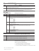
Ram (Screw) Position Transducer Configuration (other injection head)
The module accesses data in MCC09-16 if bit patterns in MCC02, 03
indicate that the module is connected to a ram (screw) position sensor.
Word Description
MCC23 Minimum Ram (Screw) Position [11]
MCC24 Maximum Ram (Screw) Position [11]
MCC25 Analog Signal at Minimum Ram (Screw) Position [24]
MCC26 Analog Signal at Maximum Ram (Screw) Position [24] The module continuously compares real-time ram (screw) position against
this entry. The module sets alarm status bit SYS07-B00 and forces all of its outputs to zero when executing a ram (screw) forward
profile (Injection, Pack, Hold) and ram (screw) position is less than or equals this entry. A zero entry inhibits SYS07-B00.
MCC27-29 RFU
MCC30 Ram (Screw) Position Transducer Digital Filter [23] A non-zero entry forces the module to filter the input before using the result for
ram (screw) position calculations. Use this parameter when required to soften the input signal from a linear potentiometer.
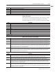
Screw RPM Transducer Configuration
The module accesses data in MCC51-56 if bit patterns in MCC02 and
MCC03 indicate that the module is connected to a screw RPM sensor.
Word Description
MCC51 Minimum Screw RPM [25]
MCC52 Maximum Screw RPM [25]
MCC53 Analog Signal at Minimum Screw RPM [24]
MCC54 Analog Signal at Maximum Screw RPM [24]
MCC55 High Screw RPM Alarm Setpoint [25] The module continuously compares real-time screw RPM against this entry. The module sets
alarm status bit SYS05-B03 when screw RPM equals or exceeds this entry. A zero entry inhibits SYS05-B03.
MCC56 High Screw RPM Alarm Time Delay [23] Total time the module must monitor a continuous screw RPM in excess of the non-zero
entry in all screw RPM alarm setpoints before setting the associated alarm status bit. Setpoint/bitpairs affected are:
Setpoint Alarm Status Bit
MCC55 SYS05-B03
JGC05 SYS05-B08
Use a non-zero entry in this word to filter out screw RPM spikes of short enough duration to avoid nuisance alarms.
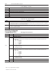
Cavity Pressure Transducer Configuration
The module accesses data in MCC57-62 if bit patterns in MCC02, 03
indicate that the module is connected to a cavity pressure sensor.
Word Description
MCC57 Minimum Cavity Pressure [04]
MCC58 Maximum Cavity Pressure [04]
MCC59 Analog Signal at Minimum Cavity Pressure [24]
MCC60 Analog Signal at Maximum Cavity Pressure [24]
MCC61 High Cavity Pressure Alarm Setpoint [04] The module continuously compares real-time cavity (or system) pressure against this entry.
The module sets alarm status bit SYS05-B04 when cavity (or system) pressure equals or exceeds this entry. A zero entry inhibits
SYS05-B04.
MCC62 High Cavity Pressure Alarm Time Delay [23] Total time the module must monitor a continuous cavity (or system) pressure in excess of
the non-zero entry in all cavity (or system) pressure alarm setpoints before setting the associated alarm status bit.
If bit patterns in MCC02 and MCC03 indicate that the module is connected to a cavity pressure sensor, setpoint/bit pairs affected are:
Setpoint Alarm Status Bit
MCC61 SYS05-B04
INC58 SYS06-B01
PKC58 SYS06-B03
HDC58 SYS06-B05
Use a non-zero entry in this word to filter out cavity pressure spikes of short enough duration to avoid nuisance alarms.