
Manual

2–28 Command Word/Bit Descriptions
Publication
1771-6.5.126 – March 1998
Notes: For [ ] engineering units, see page 2.
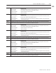
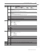
Ram (Screw) Position Transducer Configuration (own injection head)
The module accesses data in MCC09-16 if bit patterns in MCC02, 03
indicate that the module is connected to a ram (screw) position sensor.
Word Description
MCC09 Minimum Ram (Screw) Position [11]
MCC10 Maximum Ram (Screw) Position [11]
MCC11 Analog Signal at Minimum Ram (Screw) Position [24]
MCC12 Analog Signal at Maximum Ram (Screw) Position [24] The module continuously compares real-time ram (screw) position against
this entry. The module sets alarm status bit SYS07-B00 and forces all of its outputs to zero when executing a ram (screw) forward
profile (Injection, Pack, Hold) and ram (screw) position is less than or equals this entry. A zero entry inhibits SYS07-B00.
MCC13 Ram (Screw) Position Minimum Software Travel Limit [11]
MCC14 Ram (Screw) Position Maximum Software Travel Limit [11] The module continuously compares real-time ram (screw) position
against this entry. The module sets alarm status bit SYS07-B01 and forces all of its outputs to zero when executing a ram (screw)
reverse profile or movement (Pre-decompression, Plastication, Post-decompression) and ram (screw) position equals or exceeds
this entry. A zero entry inhibits SYS07-B01.
MCC15 Ram (Screw) Software Travel Limit Alarm Deadband [17] After sensing a ram (screw) overtravel and latching alarm status bit
SYS07-B00 or SYS07-B01, the module will not unlatch bit until real-time ram (screw) position is inside the overtravel setpoint by an
incremental length equal to this entry. This incremental position is added to MCC13 in order to determine ram (screw) position re-
quired to unlatch SYS07-B00. This incremental position is subtracted from MCC14 in order to determine ram (screw) position re-
quired to unlatch SYS07-B01.
MCC16 Ram (Screw) Position Transducer Digital Filter [23] A non-zero entry forces the module to filter the input before using the result for
ram (screw) position calculations. Use this parameter when required to soften the input signal from a linear potentiometer.
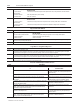
Ram (Screw) Pressure Transducer Configuration
The module accesses data in MCC17-22 if bit patterns in MCC02, 03
indicate that the module is connected to a ram (screw) pressure sensor.
Word Description
MCC17 Minimum Ram (Screw) Pressure [01]
MCC18 Maximum Ram (Screw) Pressure [01]
MCC19 Analog Signal at Minimum Ram (Screw) Pressure [24]
MCC20 Analog Signal at Maximum Ram (Screw) Pressure [24]
MCC21 High Ram (Screw) Pressure Alarm Setpoint [01] The module continuously compares real-time ram (screw) pressure against this
entry. The module sets alarm status bit SYS05-B00 when ram (screw) pressure equals or exceeds this entry. A zero entry inhibits
SYS05-B00.
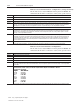
MCC22 Ram (Screw) Pressure Alarm Time Delay [23] Total time the module must monitor a continuous ram (screw) pressure in excess of
the non- ero entr in all ra ( cre ) re ure alar et oint be ore ettin the a ociated alar tatu bit.
M
CC
22
R
a
m
(
S
cre
w
) Pre
ss
ure Alar
m
Ti
m
e
D
ela
y
[
23
]
Total ti
m
e the
m
odule
m
u
s
t
m
onitor a continuou
s
ra
m
(
s
cre
w
)
p
re
ss
ure in e
x
ce
ss
o
f
the non-zero entry in all ram (screw) pressure alarm setpoints before setting the associated alarm status bit.
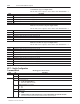
et oint bit air a ected are:
the non- ero entr in all ra ( cre ) re ure alar et oint be ore ettin the a ociated alar tatu bit.
S
et
p
oint
/
bit
p
air
s
a
ff
ected are:
etpo nt larm tatu B t
Setpoint Alarm Status Bit
M21 Y5-
M
CC
21
S
Y
S0
5-
B00
6 Y 5- 9
JGC0
6
S
Y
S0
5-
B0
9
I
N
C
57
S
Y
S0
6-
B00I
N
C
57
S
Y
S0
6-
B00
PKC57 SYS06-B02
H 57 Y 6- 4
PK 57 Y 6- 2
HDC57 SYS06-B04
P 57 Y 6- 6
P
RC
57
S
Y
S0
6-
B0
6
P 57 Y 6- 7
P
LC
57
S
Y
S0
6-
B0
7
P
SC
57
S
Y
S0
6-
B0
8
P
SC
57
S
Y
S0
6-
B0
8
Use non-zero entry to filter out ram (screw) pressure spikes of short enough duration that they should not be considered an alarm.