
Manual

2–27Command Word/Bit Descriptions
Publication
1771-6.5.126 – March 1998
MCC
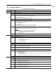
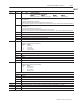
Word Bit Description
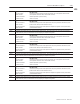
MCC02 B04-05 B05 B04 Input Configuration
nect ontrol (both bit u t be ero)
M2
4- 5
B B Input Conf gurat on
0 0 Inject Control (both bits must be zero)
Input # Input # Input # Input #
Input
#
1
Input
#
2
Input
#
3
Input
#
4
Ram (Screw) Position Ram (Screw) Pressure Screw RPM Cavity Pressure
B06 MCC02.B06 for QI(A) MCCB02.B06 for QI(B)
Configuration bit
0 = module not configured for screw RPM
1 = tells the module to verify screw RPM configuration or declare a fault
Input 3 must be connected to a sensor and this bit must be set whenever the MCC contains valid screw RPM parameters.
B07 MCC02.B07 for QI(A) MCCB02.B07 for QI(B)
Configuration bit
0 = module not configured for cavity pressure
1 = tells the module to verify cavity pressure configuration or declare a fault
Input 3 must be connected to a sensor and this bit must be set whenever MCC contains valid cavity pressure parameters.
B08 Inhibit (override) loss of sensor protection for screw position input
B09 Inhibit (override) loss of sensor protection for screw pressure input
B10-13 RFU
B14 Inhibit (override) loss of sensor protection for screw RPM input
B15 Inhibit (override) loss of sensor protection for cavity pressure input
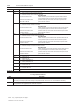
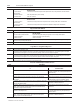
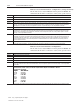
MCC03 MCC Input Range Selection
All inputs have the following range selections:
Byy Bxx Range
0 0 0 to 10 V dc
0 1 1 to 5 V dc
1 0 4 to 20 mA dc
1 1 Not Connected
Use these bit pairs to select the input range:
B01-00 Input #1
B03-02 Input #2
B05-04 Input #3
B07-06 Input #4
B08-15 Important: These bits must be SET.
MCC04 MCC Output Range Selection
All outputs have the following range selections:
Byy Bxx Range
0 0 –10 to +10 V dc
0 1 0 to +10 V dc
1 0 4 to 20 mA dc
1 1 Not Connected
Use these bit pairs to select the output range:
B01-00 Output #1
B03-02 Output #2
B05-04 Output #3
B07-06 Output #4
B08 – 15 Important: These bits must be SET.
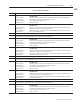
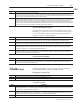
MCC05 Adds percentage offset up to "10% (–1000 to +1000) to Stop Position of Output #1 (0 V dc or 4 mA).
MCC06 Adds percentage offset up to "10% (–1000 to +1000) to Stop Position of Output #2 (0 V dc or 4 mA).
MCC07 Adds percentage offset up to "10% (–1000 to +1000) to Stop Position of Output #3 (0 V dc or 4 mA).
MCC08 Adds percentage offset up to "10% (–1000 to +1000) to Stop Position of Output #4 (0 V dc or 4 mA).