
Manual

Chapter 2
Publication
1771-6.5.126 – March 1998
Command Word/Bit
Descriptions
Command blocks provide the parameters that control machine
operation. Command blocks are transferred from the PLC processor
to the QI module by block transfer write (BTW) instructions in
software ladder logic.
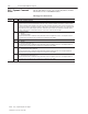
Acronym:
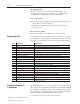
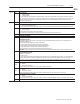
Block ID
Binary: Decimal: Description: Page:
DYC 00011001 25 Dynamic Command Block 2-4
HDC 00001011 11 Hold Configuration Block 2-10
HPC 00001100 12 Pack/Hold Profile Block 2-13
INC 00001000 8 Injection Configuration Block 2-16
IPC 00001001 9 Injection Profile Block 2-19
JGC 00000010 2 Jog Configuration Block 2-25
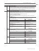
MCC 00000001 1 Module Configuration Command Block 2-26
PKC 00001010 10 Pack Configuration Block 2-30
PLC 00001110 14 Plastication Configuration Block 2-32
PPC 00001111 15 Plastication Profile Block 2-35
PRC 00001101 13 Pre-Decompression Configuration Block 2-38
PSC 00010000 16 Post-Decompression Configuration Block 2-40
PTC 00011100 28 Process Trace Configuration Block 2-41
RLC 00011010 26 Inject ERC Values Block 2-42
Refer to chapter 3 for the word/bit descriptions of status blocks.
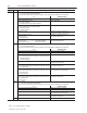
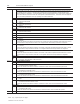
The listings of command blocks use five types of data words:
• Block ID
• Bit-mapped
• Stored-value
• Reserved (RFU)
Block ID Word
The first word in each command block contains a binary number
code in the low byte that identifies the block. The QI module uses
block IDs to identify command blocks sent from the PLC processor,
while the PLC processor uses them to identify status blocks received
from the QI module.
Alphabetical List of
Command Blocks and
Block ID Codes
List of Data Words