
Manual

1–8 Abbreviated Command and Status Blocks
Publication
1771-6.5.126 – March 1998
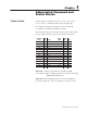
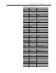
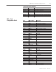
Ram(Screw) Forward-jog Set-output Values
JGC17
N40:73 Output #1
JGC18 N40:74 Output #2
JGC19 N40:75 Output #3
JGC20 N40:76 Output #4
JGC21-24 N40:77-80 RFU
Ram(Screw) Reverse-jog Set-output Values
JGC25 N40:81 Output #1
JGC26 N40:82 Output #2
JGC27 N40:83 Output #3
JGC28 N40:84 Output #4
JGC29-64 N40:85-120 RFU
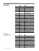
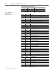
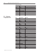
Word Pro-Set Address Description
Bit-mapped Control Words
MCC01 B34:32 Block ID 00000000 00000001
MCC02 B34:33 Module density and operating modes
MCC03 B34:34 Input range selection
MCC04 B34:35 Output range selection
Output Stop-position Adjustment
MCC05*_0** N40:1* N24:72** Output #1 stop position adjustment
MCC06*_0** N40:2 N24:73** Output #2 stop position adjustment
MCC07*_0** N40:3 N24:74** Output #3 stop position adjustment
MCC08*_0** N40:4 N24:75** Output #4 stop position adjustment
*Pro-set
600 **Pro-Set 700
For example, MCC05_0 is correct for Pro-Set 700.
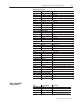
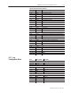
Ram (Screw) Position Sensor Configuration
MCC09 N40:5 Minimum position
MCC10 N40:6 Maximum position
MCC11 N40:7 Analog signal @ min position
MCC12 N40:8 Analog signal @ max position
MCC13 N40:9 Minimum SWTL (software travel limit)
MCC14 N40:10 Maximum SWTL
MCC15 N40:11 SWTL alarm deadband
MCC16 N40:12 Digital filter
MCC17 N40:13 Minimum pressure
MCC18 N40:14 Maximum pressure
MCC19 N40:15 Analog signal @ min pressure
MCC20 N40:16 Analog signal @ max pressure
MCC21 N40:17 High pressure alarm setpoint
MCC22 N40:18 Time delay for pressure alarms
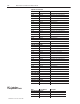
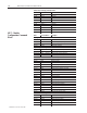
MCC43 N40:39 SWTL alarm deadband
MCC44 N40:40 Digital filter
MCC50 N40:46 Time delay for pressure alarms
Screw RPM Sensor Configuration
MCC51 N40:47 Minimum RPM
MCC52 N40:48 Maximum RPM
MCC53 N40:49 Analog signal @ min RPM
MCC54 N40:50 Analog signal @ max RPM
MCC55 N40:51 High RPM alarm setpoint
MCC56 N40:52 Time delay for RPM alarms
MCC – Module
Configuration Command
Block