
Manual

7–7Calibration Instructions
Publication
1771-6.5.126 – March 1998
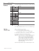
Important: Calibrate inputs before outputs. Follow this procedure for:
• calibrating the QI module’s inputs
• verifying the calibration
For each calibration below, you will:
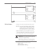
• apply precise voltages using the input wiring arm
• enter command codes in BTW word 2 with your programming
terminal
For each verification below, you will:
• apply precise voltages using the input wiring arm
• read verification codes in BTR words 10-13
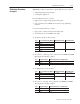
1. To calibrate the 0 to +10V dc range:
Step Enter Command Code (BTW 2): With Applied Voltage and Read in BTR:
1 0000H 000.0 word 2 = 000F
2 8000H
3 0008H
4 8008H
5 0008H 10.000 word 3 = 000F
6 8008H
2. To verify 0 to +10V range, enter command codes 0100H and 8100H.
Then apply the following voltages:
Step Apply this Voltage and Read Verification Code (BTR 10-13):
1 000.0 000H
2 5.000 800H
3 9.997 FFFH
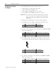
3. To calibrate the 1 to 5V dc range:
Step Enter Command Code (BTW 2): With Applied Voltage and Read in BTR
1 0010H 1.000 word 2 = 00FF
2 8010H
3 0010H 5.000 word 3 = 00FF
4 8010H
4. To verify 1 to 5V range, enter command codes 0400H and 8400H.
Then apply the following voltages:
Step Apply this Voltage and Read Verification Code (BTR 10-13):
1 1.000 000H
2 3.000 800H
3 5.000 FFFH
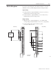
Calibration Procedure
for Inputs