
Manual
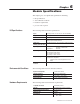
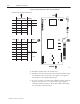

E6
E7
E8
E9
E17
E13
E14
E10
E16
E11
E15
E12
E1
TOP
BOTTOM
RIGHT
LEFT
10908-I
7–4 Calibration Instructions
Publication
1771-6.5.126 – March 1998
Figure 7.1 Jumper Settings and Locations on the Circuit Board
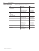
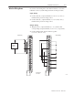
Record
Operational Jumper Settings Here:
Operational Setting Calibration
Jumper Left Right Left Right
E1
X
E6 Current Voltage
E7
E8
E9
Jumper Top Bottom Top Bottom
E10 Current Voltage
E14
E13
E17
E11 –10 to 0 to 10V
E12 +10 V or
E15 4-20mA
E16
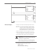
5. Install the circuit board on an extender card.
6. Install the extender card and circuit board in the I/O chassis using
the module slot that corresponds to the address you assigned to
the module in your calibration ladder logic.
7. If you do not have an extender card, install the circuit board in the
right-most module slot so you can access the jumper plugs by
reaching inside the I/O chassis. The module address must match
the slot location in the I/O chassis.