
Manual

7–2 Calibration Instructions
Publication
1771-6.5.126 – March 1998
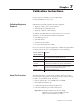
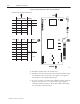
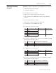
Create BTR and BTW calibration data blocks in your PLC-5 data table.
word BTW file description
1 – 1C ID that you enter
2 Command Word Command codes that you enter
3 Output 1 Codes that you enter during the calibration procedure
4 Output 2
5 Output 3
6 Output 4
word BTR file description
1 Status 0A Status and ID that you observe
2 – Min Input Values that you observe during the calibration procedure
3 – Max Input
4 – Min Output
5 – Max Output
6 Actual Input 1 Raw data from D/A converter (useful but not required during calibration)
7 Actual Input 2
8 Actual Input 3
9 Actual Input 4
10 Calibrated Input 1 Values that you observe during the calibration procedure
11 Calibrated Input 2
12 Calibrated Input 3
13 Calibrated Input 4
15 Echo of your command Indicates the transfer of data blocks
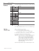
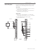
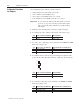
Record BTR and BTW file addresses for use in your calibration logic.
Write your calibration logic as follows:
1. Write unconditional BTW and BTR instructions
(use a block length of 0 for processor-controlled length).
2. Unlatch BTW and BTR enable bits with BTW and BTR done bits.
3. Assign the module address and data table addresses.
Important: The module address of your BTR and BTW instructions
depends on the location of the QI module in the I/O
chassis. If you do not have an extender card that lets
you access jumpers on the QI module circuit board,
place the module in the right-most slot and access the
jumpers from inside the I/O chassis. Change the slot
block transfer address to match the I/O chassis slot
location of the module.
We present example calibration logic for instructional purposes only.
Map Your BTW and BTR
Data Blocks
Wr
i
te
Your
Calibration Logic