
Manual
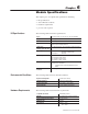

Chapter 7
Publication
1771-6.5.126 – March 1998
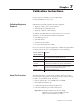
Calibration Instructions
Use this section to calibrate your 1771-QI module.
You should calibrate it once a year.
Calibrate the QI module with the following equipment:
• digital dc voltage source (1 mV accuracy)
• Allen-Bradley programming device
• digital dc voltmeter (1 mV accuracy)
To calibrate the QI module in a location away from your control
application, we recommend this additional equipment:
• spare PLC-5 processor
• spare I/O chassis
• extender card (1771-EX)
• two spare wiring arms (1771-WF)
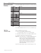
If you do not have the optional equipment to calibrate the QI module in
a location away from your control application, do the following:
If you do not have this
optional equipment:
you must:
PLC-5 processor inhibit your application program with jump/label instructions (Jump
prior to the first rung to a label after the last rung)
I/O chassis remove all I/O modules from the application I/O chassis
two wiring arms
(1771-WF)
• disconnect application wiring, then rewire after calibration
• rewire for input calibration, then rewire for output calibration
extender card
(1771-EX)
install the QI module (without covers) in the right-most I/O slot, so
you can access the jumper plugs from inside the I/O chassis
(removing the module invalidates the procedure)
digital DC voltmeter omit verifying calibration accuracy
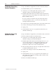
The QI module has no potentiometers to adjust. Instead, you apply
precision input voltages and corresponding reference values to the QI
module so it can calibrate itself. You must:
• map two data blocks: one for BTW and one for BTR
• write calibration ladder logic
• set internal jumpers beforehand and afterwards
• follow the calibration procedures without error
Important: If the QI module detects an error during
calibration, it reports it in the BTR status byte.
Then you must restart the procedure.
Cal
ib
rat
i
on
E
qu
i
pment
Required
Ab
out
Th
is P
rocedure