
Manual

5–7Sequencing Co-injection
Publication
1771-6.5.126 – March 1998
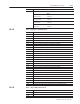
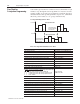
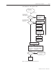
Flow Chart for A in Sequence ABA
DYC03-B04 = 1
IPC02-B10 = 1
W
ait for other screw
to reach position IPC08.
Use set-outputs INC61-64
during suspension.
TRUE
Set to suspend start
until other screw
reaches position IPC08.
FALSE
Set to enable suspension
when own screw reaches
position IPC56.
TRUE
FALSE
Run Injection Cycle
with set-outputs INC09-16
Suspend
Injection Cycle
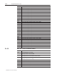
W
ait for other screw
to reach position IPC08.
Use set-outputs INC61-64
during suspension.
Other screw’
s
Position v
IPC08
T
ime Delay
IPC07
T
imer = 0
Run (resume) Injection Cycle
with set-outputs INC09-16
Start
Pack/Hold
Cycle
disable auto
to Pack/Hold
IPC02-B08 = 1
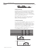
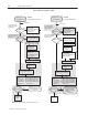
Injection ends with transition condition, 1st of:
– time
(IPC60) indicated by IPS06-B0
– screw position
(IPC61) indicated by IPS06-B1
– screw pressure
(IPC62) indicated by IPS06-B2
– cavity pressure
(IPC63) indicated by IPS06-B3
TRUE
FALSE
Own screw
Position v
IPC56
Start Injection
(DYC02
-B04 = 1)
Note:
Screw position values decrease going toward the mold.
Terminate injection cycle.
Use set-outputs INC33-36.
SYS21-B04 = 1
SYS03-B00 = 1
SYS03-B00 = 1
SYS02-B04 = 1
SYS22-B04 = 1
SYS21-B04 = 0