
User Manual
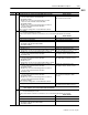
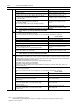
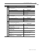
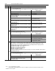
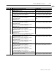
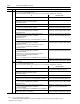
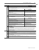
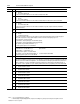

Table Of Contents
- 1771-6.5.88, Plastic Molding Module Reference Manual
- Summary of Changes
- Table of Contents
- Preface
- 1 - Abbreviated Command and Status Blocks
- Chapter Contents
- CLC - Clamp and Eject ERC Values Block
- CPC - Clamp Close Profile Block
- DYC - Dynamic Command Block
- EAC - Ejector Advance Configuration Block
- EPC - Ejector Profile Block
- ERC - Ejector Retract Configuration Block
- FCC - First Clamp Close Configuration Block
- FOC - First Clamp Open Configuration Block
- HDC - Hold Configuration Block
- HPC - Pack/Hold Profile Block
- INC - Injection Configuration Block
- IPC - Injection Profile Block
- JGC - Jog Configuration Block
- LPC - Clamp Low Pressure Close Configuration Block
- MCC - Module Configuration Command Block
- OPC - Clamp Open Profile Block
- OSC - Clamp Open Slow Configuration Block
- PKC - Pack Configuration Block
- PLC - Plastication Configuration Block
- PPC - Plastication Profile Block
- PRC - Pre-decompression Configuration Block
- PSC - Post- decompression Configuration Block
- PTC - Process Trace Configuration Block
- RLC - Inject ERC Values Block
- SCC - Second Clamp Close Configuration Block
- SOC - Second Clamp Open Configuration Block
- TCC - Third Clamp Close Configuration Block
- TOC - Third Clamp Open Configuration Block
- CLS - Clamp and Eject ERC Values Status Block
- CPS - Clamp Close Profiles Status Block
- EPS - Ejector Profile Status Block
- HPS - Pack/Hold Profile Status Block
- IPS - Injection Profile Status Block
- OPS - Clamp Open Profiles Status Block
- PPS - Plastication Profile Status Block
- PTS - Process Trace Status Block
- RLS - Inject ERC Values Status Block
- SYS - System Status Block
- 2 - Command Word/Bit Descriptions
- Alphabetical List of Command Blocks and Block ID Codes
- List of Data Words
- Engineering Units
- Data Blocks Require I/O Configuration
- Data Blocks for System Control
- Data Blocks for Controlling Ram (Screw) Position
- Data Blocks for Controlling Clamp Position
- Data Blocks for Controlling Ejector Position
- Sensors Required
- CLC CLC - Clamp and Eject ERC Values Block
- CPC - Clamp Close Profile Block
- DYC DYC - Dynamic Command Block
- EAC - Ejector Advance Configuration Block
- EPC - Ejector Profile Block
- ERC - Ejector Retract Configuration Block
- FCC - First Clamp Close Configuration Block
- FOC - First Clamp Open Configuration Block
- HDC - Hold Configuration Block
- HPC - Pack/Hold Profile Block
- INC - Injection Configuration Block
- IPC - Injection Profile Block
- JGC - Jog Configuration Block
- LPC - Clamp Low Pressure Close Configuration Block
- MCC - Module Configuration Command Block
- OPC - Clamp Open Profile Block
- OSC - Clamp Open Slow Configuration Block
- PKC - Pack Configuration Block
- PLC Plastication Configuration Command Block (PLC)
- PPC - Plastication Profile Block
- PRC - Pre-decompression Configuration Block
- PSC - Post-decompression Configuration Block
- PTC - Process Trace Configuration Block
- RLC - Inject ERC Values Block
- SCC - Second Clamp Close Configuration Block
- SOC - Second Clamp Open Configuration Block
- TCC - Third Clamp Close Configuration Block
- TOC - Third Clamp Open Configuration Block
- 3 - Word/Bit Descriptions
- List of Status Blocks and Block ID Codes
- List of Data Words
- Data Blocks Require I/O Configuration
- Engineering Units
- Status Block for Reporting System Status
- Status Blocks for Reporting Ram (Screw) Position
- Status Blocks for Reporting Clamp Position
- Status Blocks for Reporting Ejector Position
- CLS - Clamp and Eject ERC Values Status Block
- CPS - Clamp Close Profiles Status Block
- EPS - Ejector Profile Status Block
- HPS - Pack/Hold Profile Status Block
- IPS ú Injection Profile Status Block
- OPS - Clamp Open Profiles Status Block
- PPS - Plastication Profile Status Block
- PTS - Process Trace Status Block
- RLS - Inject ERC Values Status Block
- SYS - System Status Block
- 4 - Programming Error Codes
- 5 - Module Specifications
- 6 - Calibration Instructions
- A - Single transfer for Reporting Ejector Status
- Back cover

2–21Command Word/Bit Descriptions
Publication
1771-6.5.88 – July 1997
DYC
Word Bit Description
DYC02 B13 if: then the module:
= 0 Normal
= 1 Execute Clamp Open Slow Profile
A false-to-true transition of this bit forces the module to do
one
of the following, attempted in the order listed.
if: then the module:
any of SYS07-B00 through B05 are SET ignores any profile commands
SYS16-B04 is RESET latches SYS13-B14
all of the following are true:
– OPC38 is not zero
– clamp position is less than OPC38
Also occurs for clamp position less than OPC62 but not less than OPC61.
terminates any action in progress (except ongoing
Ejector Profile) and starts Clamp Open Slow Profile
clamp position equals or exceeds OPC62
terminates any action in progress (except ongoing
Ejector Profile) and sets outputs to OSC33 - OSC40
B14 = 0 Normal
= 1 Execute Ejector Profile
A false-to-true transition of this bit forces the module to do
one
of the following, attempted in the order listed.
if: then the module:
any of SYS07-B00 through B05, SYS21-B00 through B03,
or EPC03-B09 is SET, or EPC64 is zero
ignores any profile commands
EPC03-B09 is zero and
clamp position equals or is less than EPC62
latches alarm status bit SYS14-B09
SYS16-B07 is RESET latches SYS13-B15
clamp position equals or is less than EPC62 during the Ejector
Profile or while the Ejector Profile is in the
stop-and-notify
mode
with EPC03-B12 and SYS03-B08 both SET
ceases all action execution,
sets its outputs to zero, and
sets alarm status bit SYS14-B09
clamp position exceeds EPC62
terminates any action in progress (except ongoing
Clamp Open Profiles) and starts the Ejector Profile
B15 Stop Command
= 0 Outputs Enabled
= 1 Outputs Disabled
When the module decodes a valid DYC having this bit SET, it halts any ongoing profile or jog movement and set its outputs to
zero. The module will not respond to any new jog or profile execution commands as long as this bit remains SET. This bit may
be latched by the end user to serve as a module Stop command, or may be momentarily asserted to force the module to
terminate an ongoing profile.
DYC03 Timer Reset Commands
B00 = 0 Normal
= 1 Reset Tonnage Watchdog Timer
A false-to-true transition of this bit forces the module to zero the accumulated value of the Tonnage Watchdog Timer in SYS57.
B01 = 0 Normal
= 1 Reset Cure Timer
A false-to-true transition of this bit forces the module to:
reset master status bit SYS03-B03, reset master status bit SYS03-B05, and reset SYS58 to zero
B02-
B07
Open