
User Manual
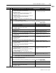
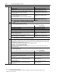
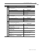
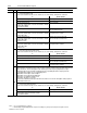
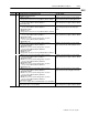
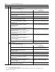
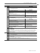
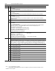

Table Of Contents
- 1771-6.5.88, Plastic Molding Module Reference Manual
- Summary of Changes
- Table of Contents
- Preface
- 1 - Abbreviated Command and Status Blocks
- Chapter Contents
- CLC - Clamp and Eject ERC Values Block
- CPC - Clamp Close Profile Block
- DYC - Dynamic Command Block
- EAC - Ejector Advance Configuration Block
- EPC - Ejector Profile Block
- ERC - Ejector Retract Configuration Block
- FCC - First Clamp Close Configuration Block
- FOC - First Clamp Open Configuration Block
- HDC - Hold Configuration Block
- HPC - Pack/Hold Profile Block
- INC - Injection Configuration Block
- IPC - Injection Profile Block
- JGC - Jog Configuration Block
- LPC - Clamp Low Pressure Close Configuration Block
- MCC - Module Configuration Command Block
- OPC - Clamp Open Profile Block
- OSC - Clamp Open Slow Configuration Block
- PKC - Pack Configuration Block
- PLC - Plastication Configuration Block
- PPC - Plastication Profile Block
- PRC - Pre-decompression Configuration Block
- PSC - Post- decompression Configuration Block
- PTC - Process Trace Configuration Block
- RLC - Inject ERC Values Block
- SCC - Second Clamp Close Configuration Block
- SOC - Second Clamp Open Configuration Block
- TCC - Third Clamp Close Configuration Block
- TOC - Third Clamp Open Configuration Block
- CLS - Clamp and Eject ERC Values Status Block
- CPS - Clamp Close Profiles Status Block
- EPS - Ejector Profile Status Block
- HPS - Pack/Hold Profile Status Block
- IPS - Injection Profile Status Block
- OPS - Clamp Open Profiles Status Block
- PPS - Plastication Profile Status Block
- PTS - Process Trace Status Block
- RLS - Inject ERC Values Status Block
- SYS - System Status Block
- 2 - Command Word/Bit Descriptions
- Alphabetical List of Command Blocks and Block ID Codes
- List of Data Words
- Engineering Units
- Data Blocks Require I/O Configuration
- Data Blocks for System Control
- Data Blocks for Controlling Ram (Screw) Position
- Data Blocks for Controlling Clamp Position
- Data Blocks for Controlling Ejector Position
- Sensors Required
- CLC CLC - Clamp and Eject ERC Values Block
- CPC - Clamp Close Profile Block
- DYC DYC - Dynamic Command Block
- EAC - Ejector Advance Configuration Block
- EPC - Ejector Profile Block
- ERC - Ejector Retract Configuration Block
- FCC - First Clamp Close Configuration Block
- FOC - First Clamp Open Configuration Block
- HDC - Hold Configuration Block
- HPC - Pack/Hold Profile Block
- INC - Injection Configuration Block
- IPC - Injection Profile Block
- JGC - Jog Configuration Block
- LPC - Clamp Low Pressure Close Configuration Block
- MCC - Module Configuration Command Block
- OPC - Clamp Open Profile Block
- OSC - Clamp Open Slow Configuration Block
- PKC - Pack Configuration Block
- PLC Plastication Configuration Command Block (PLC)
- PPC - Plastication Profile Block
- PRC - Pre-decompression Configuration Block
- PSC - Post-decompression Configuration Block
- PTC - Process Trace Configuration Block
- RLC - Inject ERC Values Block
- SCC - Second Clamp Close Configuration Block
- SOC - Second Clamp Open Configuration Block
- TCC - Third Clamp Close Configuration Block
- TOC - Third Clamp Open Configuration Block
- 3 - Word/Bit Descriptions
- List of Status Blocks and Block ID Codes
- List of Data Words
- Data Blocks Require I/O Configuration
- Engineering Units
- Status Block for Reporting System Status
- Status Blocks for Reporting Ram (Screw) Position
- Status Blocks for Reporting Clamp Position
- Status Blocks for Reporting Ejector Position
- CLS - Clamp and Eject ERC Values Status Block
- CPS - Clamp Close Profiles Status Block
- EPS - Ejector Profile Status Block
- HPS - Pack/Hold Profile Status Block
- IPS ú Injection Profile Status Block
- OPS - Clamp Open Profiles Status Block
- PPS - Plastication Profile Status Block
- PTS - Process Trace Status Block
- RLS - Inject ERC Values Status Block
- SYS - System Status Block
- 4 - Programming Error Codes
- 5 - Module Specifications
- 6 - Calibration Instructions
- A - Single transfer for Reporting Ejector Status
- Back cover

2–16 Command Word/Bit Descriptions
Publication
1771-6.5.88 – July 1997
Notes: 1. For [ ] engineering units, see page 3.
2. When using the Inject/Clamp/Eject mode, all pressure readings are system pressure at input 2, except where noted.
DYC02
B02 if: then the module:
If clamp position exceeds CPC61
and
all within any box are true: then the module:
– CPC29 is not zero
– clamp position exceeds a non-zero entry in CPC29, CPC32, or CPC35
terminates any action in progress and
starts Third Clamp Close Profile (see note)
– CPC29 is zero or is not zero when clamp position is less than all
non-zero entries in CPC29, CPC32, and CPC35
– CPC03-B10 is SET
terminates any action in progress and
sets outputs to TCC33 - TCC40 (see note)
– CPC29 is zero or is not zero when clamp position is less than all
non-zero entries in CPC29, CPC32, and CPC35
– CPC03-B10 is RESET
Also occurs when clamp position exceeds CPC62 but not CPC61.
terminates any action in progress and
starts Low Pressure Clamp Close Profile
(see note)
clamp position equals or is less than CPC62
terminates any action in progress and
sets outputs to LPC33 - LPC40 (see note)
Note: If ejector position exceeds EPC63, the module ceases all action execution,
sets its outputs to zero, and sets alarm status bit SYS14-B08.
B03 = 0 Normal
= 1 Execute Low Pressure Clamp Close Profile
A false-to-true transition of this bit forces the module to do
one
of the following, attempted in the order listed.
if: then the module:
any of SYS07-B00 through B05 are SET ignores any profile commands
ejector position exceeds EPC63 latches alarm status bit SYS14-B08
SYS15-B06 is RESET latches SYS13-B04
If all within any bo
x
are true: then the module:
– CPC38 is not zero
– clamp position exceeds CPC38
Also occurs if clamp position exceeds CPC62 but not CPC61.
terminates any action in progress and
starts Low Pressure Clamp Close Profile
(see note)
clamp position equals or is less than CPC62
terminates any action in progress and
sets outputs to LPC33 - LPC40 (see note)
Note: If ejector position exceeds EPC63, the module ceases all action execution,
sets its outputs to zero, and sets alarm status bit SYS14-B08.
Ram (Screw) Profiles Execution Commands
Bits DYC02-B04 - DYC02-B09 are the six
action execution
commands available to initiate all profiled ram (screw) movements
(including both decompression movements). You may logically link all six in a single integrated machine movement if all three
Logical Bridge Bits are RESET. These three bits are:
HPC03-B08 - Link Inj/Pack/Hold and Pre-decompress (Inj/Pack/Hold always linked)
HPC03-B09 - Link Pre-decompress and Plastication
PPC03-B08 - Link Plastication and Post-decompress
If all three of these bits are RESET, transfer only DYC02-B04 to the module to force the entire Ram (Screw) portion of an
automatic machine cycle.
B04
= 0 Normal
= 1 Execute Injection Profile
A false-to-true transition of this bit forces the module to do
one
of the following, attempted in the order listed.
if: then the module:
any of SYS07-B00 through B05 are SET ignores any profile commands
SYS15-B08 is RESET latches SYS13-B05
either of the following are true:
– ram (screw) position exceeds non-zero IPC61
– IPC61 is zero
terminates any action in progress and
starts the Injection Profile
both of the following are true:
– ram (screw) position equals or is less than non-zero IPC61
– HPC11 is not zero
terminates any action in progress and
starts the Pack Profile
both of the following are true:
– ram (screw) position equals or is less than non-zero IPC61
– HPC11 is zero
terminates any action in progress and
starts the Hold Profile