
User Manual
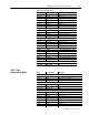
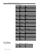
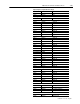
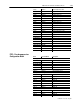
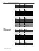
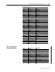
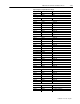
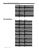
Table Of Contents
- 1771-6.5.88, Plastic Molding Module Reference Manual
- Summary of Changes
- Table of Contents
- Preface
- 1 - Abbreviated Command and Status Blocks
- Chapter Contents
- CLC - Clamp and Eject ERC Values Block
- CPC - Clamp Close Profile Block
- DYC - Dynamic Command Block
- EAC - Ejector Advance Configuration Block
- EPC - Ejector Profile Block
- ERC - Ejector Retract Configuration Block
- FCC - First Clamp Close Configuration Block
- FOC - First Clamp Open Configuration Block
- HDC - Hold Configuration Block
- HPC - Pack/Hold Profile Block
- INC - Injection Configuration Block
- IPC - Injection Profile Block
- JGC - Jog Configuration Block
- LPC - Clamp Low Pressure Close Configuration Block
- MCC - Module Configuration Command Block
- OPC - Clamp Open Profile Block
- OSC - Clamp Open Slow Configuration Block
- PKC - Pack Configuration Block
- PLC - Plastication Configuration Block
- PPC - Plastication Profile Block
- PRC - Pre-decompression Configuration Block
- PSC - Post- decompression Configuration Block
- PTC - Process Trace Configuration Block
- RLC - Inject ERC Values Block
- SCC - Second Clamp Close Configuration Block
- SOC - Second Clamp Open Configuration Block
- TCC - Third Clamp Close Configuration Block
- TOC - Third Clamp Open Configuration Block
- CLS - Clamp and Eject ERC Values Status Block
- CPS - Clamp Close Profiles Status Block
- EPS - Ejector Profile Status Block
- HPS - Pack/Hold Profile Status Block
- IPS - Injection Profile Status Block
- OPS - Clamp Open Profiles Status Block
- PPS - Plastication Profile Status Block
- PTS - Process Trace Status Block
- RLS - Inject ERC Values Status Block
- SYS - System Status Block
- 2 - Command Word/Bit Descriptions
- Alphabetical List of Command Blocks and Block ID Codes
- List of Data Words
- Engineering Units
- Data Blocks Require I/O Configuration
- Data Blocks for System Control
- Data Blocks for Controlling Ram (Screw) Position
- Data Blocks for Controlling Clamp Position
- Data Blocks for Controlling Ejector Position
- Sensors Required
- CLC CLC - Clamp and Eject ERC Values Block
- CPC - Clamp Close Profile Block
- DYC DYC - Dynamic Command Block
- EAC - Ejector Advance Configuration Block
- EPC - Ejector Profile Block
- ERC - Ejector Retract Configuration Block
- FCC - First Clamp Close Configuration Block
- FOC - First Clamp Open Configuration Block
- HDC - Hold Configuration Block
- HPC - Pack/Hold Profile Block
- INC - Injection Configuration Block
- IPC - Injection Profile Block
- JGC - Jog Configuration Block
- LPC - Clamp Low Pressure Close Configuration Block
- MCC - Module Configuration Command Block
- OPC - Clamp Open Profile Block
- OSC - Clamp Open Slow Configuration Block
- PKC - Pack Configuration Block
- PLC Plastication Configuration Command Block (PLC)
- PPC - Plastication Profile Block
- PRC - Pre-decompression Configuration Block
- PSC - Post-decompression Configuration Block
- PTC - Process Trace Configuration Block
- RLC - Inject ERC Values Block
- SCC - Second Clamp Close Configuration Block
- SOC - Second Clamp Open Configuration Block
- TCC - Third Clamp Close Configuration Block
- TOC - Third Clamp Open Configuration Block
- 3 - Word/Bit Descriptions
- List of Status Blocks and Block ID Codes
- List of Data Words
- Data Blocks Require I/O Configuration
- Engineering Units
- Status Block for Reporting System Status
- Status Blocks for Reporting Ram (Screw) Position
- Status Blocks for Reporting Clamp Position
- Status Blocks for Reporting Ejector Position
- CLS - Clamp and Eject ERC Values Status Block
- CPS - Clamp Close Profiles Status Block
- EPS - Ejector Profile Status Block
- HPS - Pack/Hold Profile Status Block
- IPS ú Injection Profile Status Block
- OPS - Clamp Open Profiles Status Block
- PPS - Plastication Profile Status Block
- PTS - Process Trace Status Block
- RLS - Inject ERC Values Status Block
- SYS - System Status Block
- 4 - Programming Error Codes
- 5 - Module Specifications
- 6 - Calibration Instructions
- A - Single transfer for Reporting Ejector Status
- Back cover
1–24 Abbreviated Command and Status Blocks
Publication
1771-6.5.88 – July 1997
Acceleration Ramp Rates
PKC17
N44:133 Output #1
PKC18 N44:134 Output #2
PKC19 N44:135 Output #3
PKC20 N44:136 Output #4
PKC21 N44:137 Output #5
PKC22 N44:138 Output #6
PKC23 N44:139 Output #7
PKC24 N44:140 Output #8
Deceleration Ramp Rates
PKC25 N44:141 Output #1
PKC26 N44:142 Output #2
PKC27 N44:143 Output #3
PKC28 N44:144 Output #4
PKC29 N44:145 Output #5
PKC30 N44:146 Output #6
PKC31 N44:147 Output #7
PKC32 N44:148 Output #8
PKC33-40 N44:149-156 RFU
Ram (Screw) Pressure Control Limits
PKC41 N44:157 Minimum limit
PKC42 N44:158 Maximum limit
PKC43 N44:159 % output for minimum
PKC44 N44:160 % output for maximum
Cavity Pressure Control Limits
PKC45 N44:161 Minimum limit
PKC46 N44:162 Maximum limit
PKC47 N44:163 % output for minimum
PKC48 N44:164 % output for maximum
Profile Tuning Constants
PKC49 N44:165 Proportional gain, ram (screw) pressure control
PKC50 N44:166 Integral gain, ram (screw) pressure control
PKC51 N44:167 Derivative gain, ram (screw) pressure control
PKC52 N44:168 Proportional gain, cavity pressure control
PKC53 N44:169 Integral gain, cavity pressure control
PKC54 N44:170 Derivative gain, cavity pressure control
Setpoints for Profile Pressure Alarms
PKC55-56 N44:171-172 RFU
PKC57 N44:173 High ram (screw) pressure alarm
PKC58 N44:174 High cavity pressure alarm
PKC59-64 N44:175-180 RFU
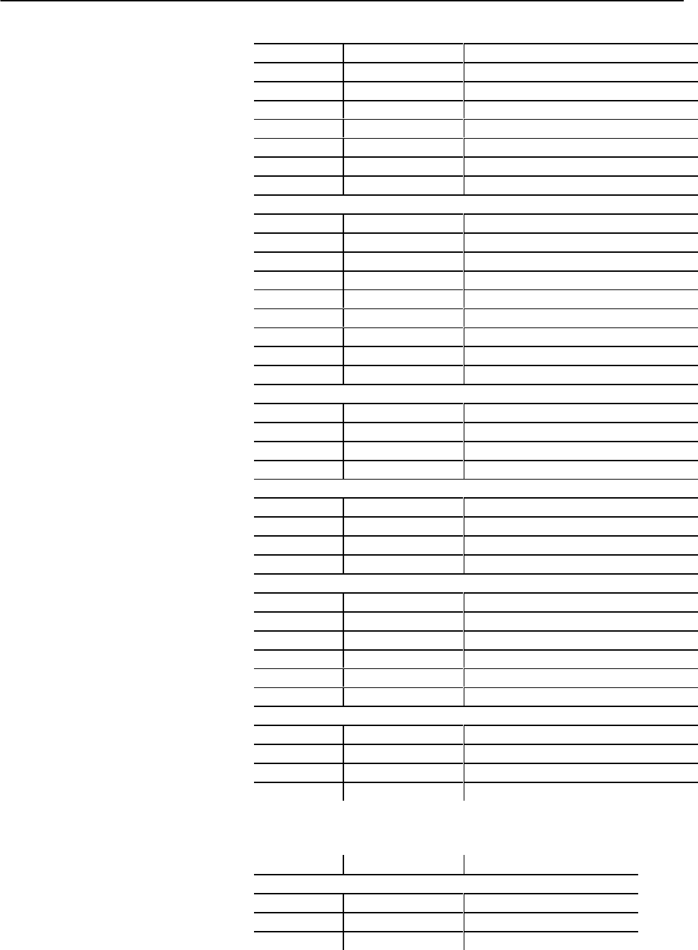
Word Pro-Set Address Description
Bit-mapped Control Words
PLC01 B38:24 Block ID 00000000 00001110
PLC02 B38:25 Selected valve configurations
PLC03-04 B38:26-27 RFU
PLC – Plastication
Configuration Block