
User Manual
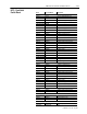
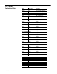
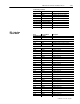
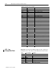

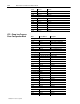
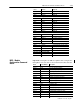
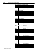
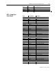
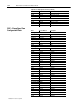
Table Of Contents
- 1771-6.5.88, Plastic Molding Module Reference Manual
- Summary of Changes
- Table of Contents
- Preface
- 1 - Abbreviated Command and Status Blocks
- Chapter Contents
- CLC - Clamp and Eject ERC Values Block
- CPC - Clamp Close Profile Block
- DYC - Dynamic Command Block
- EAC - Ejector Advance Configuration Block
- EPC - Ejector Profile Block
- ERC - Ejector Retract Configuration Block
- FCC - First Clamp Close Configuration Block
- FOC - First Clamp Open Configuration Block
- HDC - Hold Configuration Block
- HPC - Pack/Hold Profile Block
- INC - Injection Configuration Block
- IPC - Injection Profile Block
- JGC - Jog Configuration Block
- LPC - Clamp Low Pressure Close Configuration Block
- MCC - Module Configuration Command Block
- OPC - Clamp Open Profile Block
- OSC - Clamp Open Slow Configuration Block
- PKC - Pack Configuration Block
- PLC - Plastication Configuration Block
- PPC - Plastication Profile Block
- PRC - Pre-decompression Configuration Block
- PSC - Post- decompression Configuration Block
- PTC - Process Trace Configuration Block
- RLC - Inject ERC Values Block
- SCC - Second Clamp Close Configuration Block
- SOC - Second Clamp Open Configuration Block
- TCC - Third Clamp Close Configuration Block
- TOC - Third Clamp Open Configuration Block
- CLS - Clamp and Eject ERC Values Status Block
- CPS - Clamp Close Profiles Status Block
- EPS - Ejector Profile Status Block
- HPS - Pack/Hold Profile Status Block
- IPS - Injection Profile Status Block
- OPS - Clamp Open Profiles Status Block
- PPS - Plastication Profile Status Block
- PTS - Process Trace Status Block
- RLS - Inject ERC Values Status Block
- SYS - System Status Block
- 2 - Command Word/Bit Descriptions
- Alphabetical List of Command Blocks and Block ID Codes
- List of Data Words
- Engineering Units
- Data Blocks Require I/O Configuration
- Data Blocks for System Control
- Data Blocks for Controlling Ram (Screw) Position
- Data Blocks for Controlling Clamp Position
- Data Blocks for Controlling Ejector Position
- Sensors Required
- CLC CLC - Clamp and Eject ERC Values Block
- CPC - Clamp Close Profile Block
- DYC DYC - Dynamic Command Block
- EAC - Ejector Advance Configuration Block
- EPC - Ejector Profile Block
- ERC - Ejector Retract Configuration Block
- FCC - First Clamp Close Configuration Block
- FOC - First Clamp Open Configuration Block
- HDC - Hold Configuration Block
- HPC - Pack/Hold Profile Block
- INC - Injection Configuration Block
- IPC - Injection Profile Block
- JGC - Jog Configuration Block
- LPC - Clamp Low Pressure Close Configuration Block
- MCC - Module Configuration Command Block
- OPC - Clamp Open Profile Block
- OSC - Clamp Open Slow Configuration Block
- PKC - Pack Configuration Block
- PLC Plastication Configuration Command Block (PLC)
- PPC - Plastication Profile Block
- PRC - Pre-decompression Configuration Block
- PSC - Post-decompression Configuration Block
- PTC - Process Trace Configuration Block
- RLC - Inject ERC Values Block
- SCC - Second Clamp Close Configuration Block
- SOC - Second Clamp Open Configuration Block
- TCC - Third Clamp Close Configuration Block
- TOC - Third Clamp Open Configuration Block
- 3 - Word/Bit Descriptions
- List of Status Blocks and Block ID Codes
- List of Data Words
- Data Blocks Require I/O Configuration
- Engineering Units
- Status Block for Reporting System Status
- Status Blocks for Reporting Ram (Screw) Position
- Status Blocks for Reporting Clamp Position
- Status Blocks for Reporting Ejector Position
- CLS - Clamp and Eject ERC Values Status Block
- CPS - Clamp Close Profiles Status Block
- EPS - Ejector Profile Status Block
- HPS - Pack/Hold Profile Status Block
- IPS ú Injection Profile Status Block
- OPS - Clamp Open Profiles Status Block
- PPS - Plastication Profile Status Block
- PTS - Process Trace Status Block
- RLS - Inject ERC Values Status Block
- SYS - System Status Block
- 4 - Programming Error Codes
- 5 - Module Specifications
- 6 - Calibration Instructions
- A - Single transfer for Reporting Ejector Status
- Back cover

1–16 Abbreviated Command and Status Blocks
Publication
1771-6.5.88 – July 1997
Setpoints for Injection Profile (continued)
IPC36
N44:92 Segment 7 time
IPC37 N44:93 Segment 8 velocity
IPC38 N44:94 Segment 8 pressure
IPC39 N44:95 End of Segment 8 position
IPC40 N44:96 Segment 8 time
IPC41 N44:97 Segment 9 velocity
IPC42 N44:98 Segment 9 pressure
IPC43 N44:99 End of Segment 9 position
IPC44 N44:100 Segment 9 time
IPC45 N44:101 Segment 10 velocity
IPC46 N44:102 Segment 10 pressure
IPC47 N44:103 End of Segment 10 position
IPC48 N44:104 Segment 10 time
IPC49 N44:105 Segment 11 velocity
IPC50 N44:106 Segment 11 pressure
Profile Offsets
IPC51 N44:107 Velocity
IPC52 N44:108 Pressure
IPC53-56 N44:109-112 RFU
Pressure Limiting Values
IPC57 N44:113 Ram (Screw) pressure, LimVel/Pos profile
IPC58 N44:114 Ram (Screw) position to begin pressure limiting
IPC59 N44:115 Time delay for change in algorithm
Transition Values
IPC60 N44:116 Time
IPC61 N44:117 Ram (Screw) position
IPC62 N44:118 Ram (Screw) pressure
IPC63 N44:119 Cavity pressure
Transition Pressure Inhibit
IPC64 N44:120 Ram (Screw) position
Important: If using Pro-Set 600 and a QDC module configured for
Clamp/Eject mode, this data is found in alternate files B35 and N41.
Word Pro-Set Address Description
Bit-mapped Control Words
JGC01 B34:36 Block ID 00000000 00000010
JGC02-04 B34:37-39 RFU
Jog Alarm Setpoints
JGC05 N40:61 Screw jog RPM alarm
JGC06 N40:62 Ram jog pressure alarm
JGC07 N40:63 Clamp jog pressure alarm
JGC08 N40:64 Ejector jog pressure alarm
JGC – Jog
Configuration Block