
User Manual
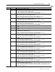
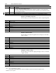
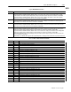
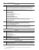
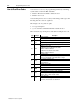
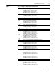
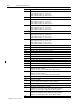
Table Of Contents
- 1771-6.5.88, Plastic Molding Module Reference Manual
- Summary of Changes
- Table of Contents
- Preface
- 1 - Abbreviated Command and Status Blocks
- Chapter Contents
- CLC - Clamp and Eject ERC Values Block
- CPC - Clamp Close Profile Block
- DYC - Dynamic Command Block
- EAC - Ejector Advance Configuration Block
- EPC - Ejector Profile Block
- ERC - Ejector Retract Configuration Block
- FCC - First Clamp Close Configuration Block
- FOC - First Clamp Open Configuration Block
- HDC - Hold Configuration Block
- HPC - Pack/Hold Profile Block
- INC - Injection Configuration Block
- IPC - Injection Profile Block
- JGC - Jog Configuration Block
- LPC - Clamp Low Pressure Close Configuration Block
- MCC - Module Configuration Command Block
- OPC - Clamp Open Profile Block
- OSC - Clamp Open Slow Configuration Block
- PKC - Pack Configuration Block
- PLC - Plastication Configuration Block
- PPC - Plastication Profile Block
- PRC - Pre-decompression Configuration Block
- PSC - Post- decompression Configuration Block
- PTC - Process Trace Configuration Block
- RLC - Inject ERC Values Block
- SCC - Second Clamp Close Configuration Block
- SOC - Second Clamp Open Configuration Block
- TCC - Third Clamp Close Configuration Block
- TOC - Third Clamp Open Configuration Block
- CLS - Clamp and Eject ERC Values Status Block
- CPS - Clamp Close Profiles Status Block
- EPS - Ejector Profile Status Block
- HPS - Pack/Hold Profile Status Block
- IPS - Injection Profile Status Block
- OPS - Clamp Open Profiles Status Block
- PPS - Plastication Profile Status Block
- PTS - Process Trace Status Block
- RLS - Inject ERC Values Status Block
- SYS - System Status Block
- 2 - Command Word/Bit Descriptions
- Alphabetical List of Command Blocks and Block ID Codes
- List of Data Words
- Engineering Units
- Data Blocks Require I/O Configuration
- Data Blocks for System Control
- Data Blocks for Controlling Ram (Screw) Position
- Data Blocks for Controlling Clamp Position
- Data Blocks for Controlling Ejector Position
- Sensors Required
- CLC CLC - Clamp and Eject ERC Values Block
- CPC - Clamp Close Profile Block
- DYC DYC - Dynamic Command Block
- EAC - Ejector Advance Configuration Block
- EPC - Ejector Profile Block
- ERC - Ejector Retract Configuration Block
- FCC - First Clamp Close Configuration Block
- FOC - First Clamp Open Configuration Block
- HDC - Hold Configuration Block
- HPC - Pack/Hold Profile Block
- INC - Injection Configuration Block
- IPC - Injection Profile Block
- JGC - Jog Configuration Block
- LPC - Clamp Low Pressure Close Configuration Block
- MCC - Module Configuration Command Block
- OPC - Clamp Open Profile Block
- OSC - Clamp Open Slow Configuration Block
- PKC - Pack Configuration Block
- PLC Plastication Configuration Command Block (PLC)
- PPC - Plastication Profile Block
- PRC - Pre-decompression Configuration Block
- PSC - Post-decompression Configuration Block
- PTC - Process Trace Configuration Block
- RLC - Inject ERC Values Block
- SCC - Second Clamp Close Configuration Block
- SOC - Second Clamp Open Configuration Block
- TCC - Third Clamp Close Configuration Block
- TOC - Third Clamp Open Configuration Block
- 3 - Word/Bit Descriptions
- List of Status Blocks and Block ID Codes
- List of Data Words
- Data Blocks Require I/O Configuration
- Engineering Units
- Status Block for Reporting System Status
- Status Blocks for Reporting Ram (Screw) Position
- Status Blocks for Reporting Clamp Position
- Status Blocks for Reporting Ejector Position
- CLS - Clamp and Eject ERC Values Status Block
- CPS - Clamp Close Profiles Status Block
- EPS - Ejector Profile Status Block
- HPS - Pack/Hold Profile Status Block
- IPS ú Injection Profile Status Block
- OPS - Clamp Open Profiles Status Block
- PPS - Plastication Profile Status Block
- PTS - Process Trace Status Block
- RLS - Inject ERC Values Status Block
- SYS - System Status Block
- 4 - Programming Error Codes
- 5 - Module Specifications
- 6 - Calibration Instructions
- A - Single transfer for Reporting Ejector Status
- Back cover

4–5Programming Error Codes
Publication
1771-6.5.88 – July 1997
Error Code
Description
ID = 1
0432
MCC32 is out of range. Valid range is MCC31 < MCC32
≤
09999
0435 MCC35 is out of range.
If non-zero, MCC35 must be within MCC31 < MCC35
≤
MCC32
0437
MCC37 is out of range. Valid range is 00000
≤
MCC37 < MCC38
0438
MCC38 is out of range. Valid range is MCC37 < MCC38
≤
09999
0441 Your non-zero entry for MCC41 is out of range.
If MCC42 is non-zero, MCC41 must be within MCC37
≤
MCC41 < MCC42
If MCC42 is zero, MCC41 must be within MCC37
≤
MCC41 < MCC38
0442 Your non-zero entry for MCC42 is out of range.
If MCC41 is non-zero, MCC42 must be within MCC41 < MCC42
≤
MCC38
If MCC41 is zero, MCC42 must be within MCC37 < MCC42
≤
MCC38
0445
MCC45 is out of range. Valid range is 00000
≤
MCC45 < MCC46
0446
MCC46 is out of range. Valid range is MCC45 < MCC46
≤
09999
0449 MCC49 is out of range.
If non-zero, MCC49 must be within MCC45 < MCC49
≤
MCC46
0451
MCC51 is out of range. Valid range is 00000
≤
MCC51 < MCC52
0452
MCC52 is out of range. Valid range is MCC51 < MCC52
≤
09999
0455 MCC55 is out of range.
If non-zero, MCC55 must be within MCC51 < MCC55
≤
MCC52
0457
MCC57 is out of range. Valid range is 00000
≤
MCC57 < MCC58
0458
MCC58 is out of range. Valid range is MCC57 < MCC58
≤
20000
0461 MCC61 is out of range.
If non-zero, MCC61 must be within MCC57 < MCC61
≤
MCC58
0502 You configured the module for 4x4 I/O by MCC02-B03 = 1.
Therefore, MCC02-B04 = 1 and MCC02-B05 = 1 is illegal.
0503 You configured the module for 4x4 I/O by MCC02-B03 = 1.
Therefore, your bit pattern in the upper byte of MCC03 must be 11111111 to indicate that
inputs #5 through #8 are “unconnected”.
0504 You configured the module for 4x4 I/O by MCC02-B03 = 1.
Therefore, your bit pattern in the upper byte of MCC04 must be 11111111 to indicate that
outputs #5 through #8 are “unconnected”.
0507 Your settings for MCC02-B03, B04, and B05 indicate that module input #1 is reserved for a
ram (screw) position transducer. Therefore MCC03-B00 and B01 cannot both = 1.
0511 Your settings for MCC02-B03, B04, and B05 indicate that module input #3 is reserved for a
clamp position transducer. Therefore MCC03-B00 and B01 cannot both = 1.
0602 You configured the module for 8x8 I/O by MCC02-B03 = 0.
This configuration is not supported by your series/revision of firmware.
0915 MCC15 is too large.
if: then:
MCC13 and MCC14 MCC15 must be within MCC13 + MCC15 < MCC14 – MCC15
are both non-zero
MCC13 is zero and MCC15 must be within MCC09 + MCC15 < MCC14 – MCC15
MCC14 is non-zero
MCC13 is non-zero MCC15 must be within MCC13 + MCC15 < MCC10 – MCC15
and MCC14 is zero
0929 MCC29 is too large.
if: then:
MCC27 and MCC28 MCC29 must be within MCC27 + MCC29 < MCC28 – MCC29
are both non-zero
MCC27 is zero and MCC29 must be within MCC23 + MCC29 < MCC28 – MCC29
MCC28 is non-zero
MCC27 is non-zero MCC29 must be within MCC27 + MCC29 < MCC24 – MCC29
and MCC28 is zero